This figure shows two meridians or parallel
lines that are intersected by another line called a
traverse. It can be proved geometrically that the
angles A and Al, B and B1, Az and A3, and Bz
and B3 are equal (vertically opposite angles).
It can also be shown that angles A = A2, and
B = B2 (corresponding angles). Therefore,
It can also be shown that the sum of the angles
that form a straight line is 180°; the sum of all
the angles around the point is 360°.
Figure 13-2 shows a traverse containing
traverse lines AB, BC, and CD. The meridians
through the traverse stations are indicated by the
lines NS, N´S´, and N´´S´´. Although meridians are
not, in fact, exactly parallel, they are assumed to
be, for conversion purposes. Consequently, we
have here three parallel lines intersected by
traverses, and the angles created will therefore be
equal, as shown in figure 13-1.
The bearing of AB is given as N20°E, which
means that angle NAB measures 20°. To deter-
mine the deflection angle between AB and BC,
you proceed as follows: If angle NAB measures
20°, then angle N’BB’ must also measure 20°
because the two corresponding angles are equal.
The bearing of BC is given as S50°E, which means
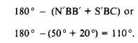
angle S´BC measures 50°E. The sum of angle
Figure 13-2.-Converting bearings to deflection angles from
given traverse data.
N´BB´ plus S´BC plus the deflection angle
between AB and BC (angle B´BC) is 180°.
Therefore, the size of the deflection angle is
The figure indicates that the angle should be
turned to the right; therefore, the complete
deflection angle description is 11°R.
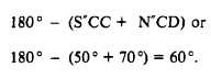
The bearing of CD is given as N70°E;
therefore, angle N´´CD measures70°. Angle S´´CC´
is equal to angle S´BC and therefore measures 50°.
The deflection angle between BC and CD equals
The figure indicates that the angle should be
turned to the left.
Converting Deflection Angles to Bearings
Converting deflection angles to bearings is
simply the same process used for a different end
result. Suppose that in figure 13-2, you know the
deflection angles and want to determine the
corresponding bearings. To do this, you must
know the bearing of at least one of the traverse
lines. Let’s assume that you know the bearing of
AB and want to determine the bearing of BC. You
know the size of the deflection angle B´BC is 110°.
The size of angle N´BB´ is the same as the size
of NAB, which is 20°. The size of the angle of
bearing of BC is
The figure shows you that BC lies in the second
or SE quadrant; therefore, the full description of
the bearing is S50°E.
Converting Bearings to Interior
and Exterior Angles
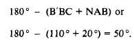
Converting a bearing to an interior or exterior
angle is, once again, the same procedure applied
for a different end result. Suppose that in figure
13-2, angle ABC is an interior angle and you want
to determine the size. You know that angle ABS´
equals angle NAB, and therefore measures 20°.
13-2