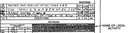
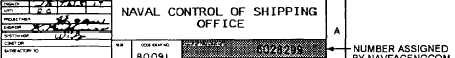
Figure 10-2.-A title block showing a drawing number assigned by NAVFACENGCOM.
(Figure 10-2 is an example of a local activity, such as
the Civil Engineering Support Office (CESO), using a
drawing number assigned by the Western
(WESTDIV).)
Figure 10-2.A title block showing a
number assigned by NAVFACENGCOM.
You may not use a NAVFACENGCOM
Division
drawing
assigned
number for any other drawing, even though the drawing
to which it has been assigned is not being used.
Sometimes, because of extensive revision on a
particular drawing, it becomes necessary to prepare a
new drawing and to assign a new NAVFACENGCOM
drawing number. A cross-reference note to be placed
directly above or adjacent to the title block is shown
below.
Old Drawing Note:
THIS DRAWING SUPER-
SEDED BY DRAWING
NO.
Drawing Revisions
New Drawing Note:
THIS DRAWING SUPER-
SEDES DRAWING
NO.
Revisions to NAVFACENGCOM project drawings
are to be made according to DOD-STD-100C. The
revision block may include a separate “PREPARED
BY” column to indicate the organization, such as an A/E
firm, that prepared the revision. The layout of the
modified revision block is to be as shown in chapter 3,
figure 3-22, views A and B.
Graphic Scales
Graphic scales are located in the lower right-hand
corner of each drawing sheet, with the words Graphic
Scales directly over them. The correct graphic scales
must be shown prominently on each drawing because,
as drawings are reduced in size, the reductions are often
NOT to scaled proportions.
Line Conventions and Lettering
You should pay close attention to the opaqueness
and uniform weight of lines. To provide contrasting
division and use of thick and thin lines, refer to chapter
3, figure 3-23, and ANSI Y14.2M, Line Conventions
and Lettering, Engineering Drawing and Related
Documentation Practices. Uppercase lettering is to be
used except for notes on maps and similar drawings,
where lowercase lettering may be used. The minimum
allowable height of freehand letters is 5/32 (0.156) in.,
and of mechanical or computer graphics is 0.150 in. For
abbreviations on drawings, use MIL-STD-12,
Abbreviations.
DIMENSIONING AND TOLERANCING
All dimensions and tolerances are to clearly define
engineering intent and be prepared according to ANSI
Y14.5M, Dimensioning and Tolerancing for
Engineering Drawings. Some of the fundamental rules
that apply to dimensioning and tolerancing drawings
are as follows:
1. A dimension having a tolerance may have it
applied directly to the dimension or indicated by a
general note on the drawing sheet.
2. Dimensioning for size, form, and location of
features are to be complete; however, no more
dimensions than those necessary for complete
definition should be given. Neither the use of “sealing”
(measuring the size of a feature directly from an
engineering drawing) nor assumption of a distance or
size is permitted. The use of a reference dimension on
a drawing should also be minimized.
3. Dimensions should be arranged to provide
optimum readability to obtain required
10-6