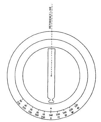
Figure 13-10.-Setting the vernier at zero-zero.
The horizontal limb is paired with another
circle (the vernier plate), which is partially
graduated on either side of zero graduations
located 180° apart on the plate. When the
telescope is in the normal (upright) position, the
A vernier is located vertically below the eyepiece,
and the B vernier, below the objective end of the
telescope. The zero on each vernier is the indicator
for reading the sizes of horizontal angles turned
on the horizontal limb.
Figures 13-10 and 13-11 illustrate the method
of turning an angle of 30° from a reference line
with a transit.
1. With the transit properly set over the point
or station, bring one of the horizontal verniers
near zero by hand; clamp the upper motion; and,
by turning the upper tangent screw, set one
vernier at 0°, usually starting with the A vernier
(fig. 13-10). Train the telescope to sight the marker
(range pole, chaining pin, or the like) held on the
reference line; clamp the lower motion; and, by
using the lower tangent screw, set the line of sight
on the marker.
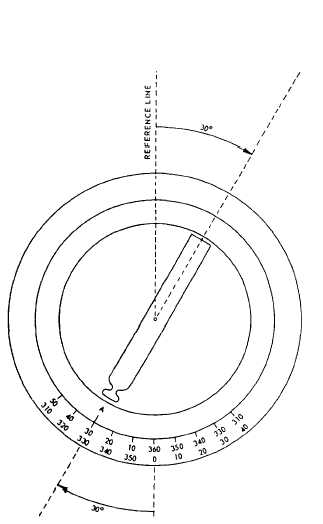
Figure 13-11.-Setting an angle exactly on the vernier zero.
2. Release the upper motion and rotate the
telescope to bring the zero on the A vernier in line
with th3 30° graduation on the horizontal limb,
as shown in figure 13-11. To set the vernier
exactly at 30°, use the upper tangent screw. You
may use a magnifying glass to set the vernier easily
and accurately.
3. Mark the next point with a marker, and
follow the procedures for establishing a point or
station.
Similarly, you may use the procedures above
to measure a horizontal angle by sighting on two
existing points and reading their interior angle.
In addition, the following hints may help you
when you are taking horizontal measurements:
1. Make the centering of the line of sight as
close as possible by hand so that you will not turn
the tangent screw more than one or two turns.
Make the last turn of the tangent screw clockwise
to compress the opposing springs.
13-10