4. You should always maintain contact
between the leveling screw shoes and the foot
plate.
5. You should not disturb the setup of the
instrument until you are certain that all observa-
tions at that point are completed and roughly
checked. You should move the instrument from
that setup only after checking with the party chief.
6. Before the transit is moved or taken up,
you should center the instrument on the foot
plate, roughly equalize the height of the leveling
screws, clamp the upper motion (the lower
motion may be tightened lightly), and point the
Measuring Horizontal Angles
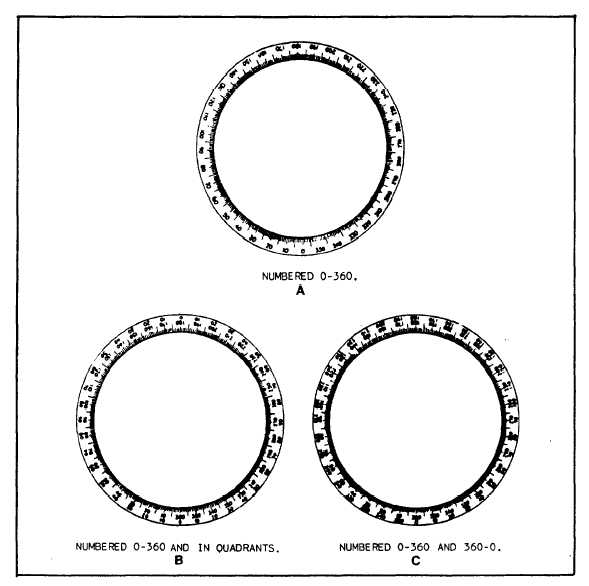
The transit contains a graduated horizontal
circle, referred to as the horizontal limb. The
horizontal limb may be graduated clockwise from
0° through 360°, as shown in figure 13-9, view
A, or clockwise from 0° through 360° and also
in quadrants, as shown in figure 13-9, view B; or
both clockwise and counterclockwise from 0°
through 360°, as shown in figure 13-9, view C.
The horizontal limb can be clamped to stay
fast when the telescope is rotated (called clamping
the lower motion), or it can be released for
telescope vertically upward and also lightly tighten
rotating by hand (called releasing the
the vertical motion clamp.
motion).
lower
Figure 13-9.-Three types of horizontal limb graduations.
13-9