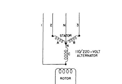
Figure 9-5.-Y-connected alternator (three-phase, four-wire).
STATOR represents the stationary coils of wire
in the alternator; the one marked ROTOR
represents the coils, which rotate on the armature.
You can see that the power is taken off the stator
from three connections, which in the drawing
form a triangle or delta. All three wires are live
(called HOT) wires.
Figure 9-5 shows a Y-connected alternator
(three-phase, four-wire). N represents a common
or NEUTRAL point to which the stator coils are
all connected. The current is taken off the stator
by the three lines (wires), 1, 2, and 3, connected
to the stator coil ends; and also by a fourth line,
N, connected to the neutral point. Lines 1, 2, and
3 are hot wires; line N is NEUTRAL.
The voltage developed in any pair of wires,
or in all three wires, in a delta-connected
alternator is always the same; therefore, a
Figure 9-6.-A pictorial view of a four-wire overhead distribution system.
9-4