recorded in the field book as they are established
in the field. The record may be done either by
sketch, by work description, or by the combina-
tion of the sketch and notes. The control point
must be referenced to some permanent type of
object in its vicinity; if no such objects exist,
REFERENCE HUBS are driven at points where
they are unlikely to be disturbed. These ties are
important in recovering control points that
have been covered or otherwise hidden or in
reestablishing them accurately if they have been
removed.
The reference location of a particular point
is recorded on the remarks page of the field book
by sketches like those shown in figures 12-8 and
12-9. For a permanent control point, such as a
triangulation point, monument, or bench mark,
a complete “Station Description” is individually
prepared for each station. The field offices of the
National Oceanic and Atmospheric Administra-
tion or the National Geological Survey have these
station descriptions on separate cards. This is done
so they can easily run a copy for anyone
requesting a description of a particular station.
They also maintain a vicinity map on which these
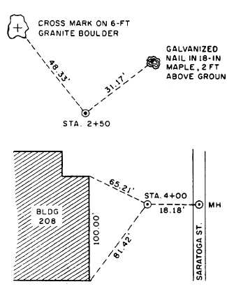
Figure 12-8.-Natural objects or man-made structures used
as reference points.
Figure 12-9.-Accurate methods for tying points.
points are plotted, and these station descriptions
are used in conjunction with this map. The Navy’s
public works offices also maintain descriptions
of stations within their naval reservation and its
vicinity for immediate reference.
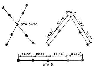
The methods of referencing points shown in
figure 12-8 are ideal for recovering points that
have been covered or otherwise hidden, and those
shown in figure 12-9 are for reestablishment of
these points accurately. The methods shown in
figure 12-9 are generally used in construction
surveys.
As you gain more experience, you may be
assigned the task of writing a station description.
In doing this, be sure to describe the location in
detail, and make a sketch showing the location,
ties, and magnetic or true meridian. Make your
description concise and clear; and be sure to test
its effectiveness by letting another EA (preferably
not a member of the survey party that established
the point) interpret your description. From the
feedback of the interpretation, you can determine
the accuracy of your written description. Your
description, for example, should be written as
follows (refer to figure 12-8): “Point A—plugged
G.I. pipe 65.21 ft SE of NE corner of PWC
Admin. Bldg. (Bldg. 208) and 81.42 ft from the
SE corner of same building. It is 18.18 ft W of
the center of a circular manhole cover located in
Saratoga Street.”
Protecting Markers
Markers are to be protected against physical
disturbance by the erection of a temporary fence
(or barricade) around them. Sometimes guard
stakes embellished with colored flaggings are
12-9