in each bent are 10 feet apart; bents are identified by
letters; and piles, by numbers. The distance between
adjacent transit setups in the base line is 10/sin 84°, or
10.05 feet.
Bents are located 20 feet apart. The distance
from the center-line base line transit setup at station
7 + 41.05 to pile No. 3 is 70 feet. The distance from
station 7 + 51.10 to pile No. 2 is 70 + 10 tan 6°, or
70 + 1.05, or 71.05 feet. The distance from station
7 + 61.15 to pile No. 1 is 71.05 + 1.05, or 72.10 feet.
The distance from station 7 + 31.00 to pile No. 4 is
70 - 1.05, or 68.95 feet; and from station 7 + 20.95 to
pile No. 5 is 68.95 – 1.05, or 67.90 feet.
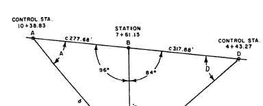
You can determine the angle you turn, at a control
station, from the base line to any pile location by
triangle solution. Consider pile No. 61, for example.
This pile is located 240 + 72.10, or 312.10 feet, from
station 7 + 61.15 on the base line. Station 7 + 61.15 is
located 1,038.83 – 761.15, or 277.68 feet, from control
station 10 + 38.83. The angle between the line from
station 7 + 61.15 through pile No. 61 and the base line
measures 180°- 84°, or 96°. Therefore, you are dealing
with the triangle ABC shown in figure 10-31. You want
to know the size of angle A. First solve for b by the law
of cosines, in which b2 = a2 + c2- 2ac cos B, as follows:
b2 = 312.102 + 277.682- 2(312.10)(277.68) cos 96°
b = 438.89 feet
Knowing the length of b, you can now determine
the size of angle A by the law of sines. Sin A = 312.10
sin 96°/438.89, or 0.70722. This means that angle A
measures, to the nearest minutes, 45°00´.
Figure 10-31.—Trigonometric solution for pile No. 61.
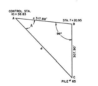
Figure 10-32.—Trigonometric solution for pile No. 65.
To determine the direction of this pile from
control station 4 + 43.27, you would solve the triangle
DBC shown in figure 10-31. You do this in the same
manner as described above. First solve for b using the
law of cosines and then solve for angle D using the
law of sines. After doing this, you find that angle D
equals 47°26´.
It would probably be necessary to locate in this
fashion only the two outside piles in each bent; the
piles between these two could be located by measuring
off the prescribed spacing on a tape stretched be-
tween the two. For the direction from control station
10 + 38.83 to pile No. 65 (the other outside pile in
bent M), you would solve the triangle shown in figure
10-32. Again, you solve for b using the law of cosines
and then use the law of sines to solve for angle A.
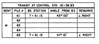
For each control station, a pile location sheet like
the one shown in figure 10-33 would be made up. If
desired, the direction angles for the piles between No.
61 and No. 65 could be computed and inserted in the
intervening spaces.
Figure 10-33.—File location sheet.
10-29