PLANE-TABLE POINTERS
One of the troublesome problems in operating a
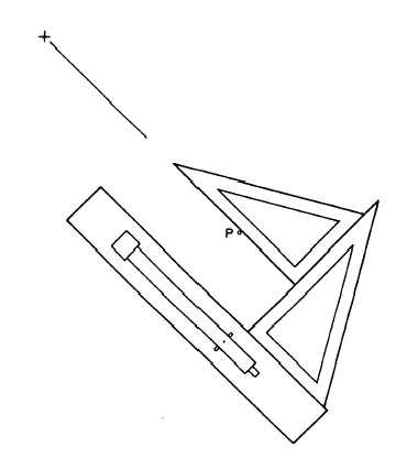
plane table is the difficulty of keeping the alidade
blade on the plotted position of the occupied point,
such as P in figure 9-9. As the alidade is moved to sight
a detail, the edge moves off point P. A solution some-
times tried is to use a pin at P and pivot around it, but
a progressively larger hole is gouged in the paper with
each sight. To eliminate this problem, use two tri-
angles to draw a parallel line with the straightedge of
the telescope over pivot point P. The small error
produced by the eccentric sight is no greater than that
resulting from not being exactly over the ground point,
P, or even that caused by the telescope axis not being
over the edge of the blade.
Other pointers that may be helpful concerning the
use of the plane table are as follows:
1. Use buff or green detail paper to lessen the
glare.
2. Plot and ink the traverse in advance of the
detailing, showing lengths of traverse lines; coordinates
of triangulation stations, if known; and useful signals
Figure 9-9.—Transfer of pivot point.
3. Have a least one vertical control for each three
hubs of a traverse, and show all known elevations.
4. Cover the portion of the map not being used.
5. Setup the table slightly below elbow height.
6. Check the orientation on two or more lines if
possible.
7. Check the distance and elevation difference in
both directions when setting a new hub.
8. Read the distance first and then the vertical
angle; or with a Beaman arc, read the H-scale and then
the V-scale.
9. To keep the paper cleaner, lift the forward end
of the alidade blade to pivot instead of sliding the blade.
10. Clean the paper frequently to remove graphite.
11. Check the location of hubs by resection and
cutting in (sighting and plotting) prominent objects.
12. Draw short lines at the estimated distances on
the map to plot points. Do not start the lines at the hub
occupied.
13. Identify points by consecutive numbers or
names as they are plotted.
14. Have the rodman make independent sketches
on long shots for later transference to the plane-table
map.
15. Use walkie-talkie sets to enable the rodmen to
describe topographic features when the observer cannot
identify them because of distance and obstacles.
16. Use the same points to locate details and
contours whenever possible.
17. Sketch contours after three points have been
plotted. Points on the maps lose their value if they
cannot be identified on the ground.
18. Show spot elevations for summits, sags,
bridges, road crossings, and all other critical points.
19. Tie a piece of colored cloth on the stadia rod at
the required rod reading to speed work in locating
contours by the direct method.
20. Use vertical aerial photographs for plane-table
sheets. The planimetric details can be checked and
contours added.
21. Use a 6H or harder pencil to avoid smudging.
9-8