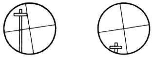
Figure 6-4.—Adjusting the plate bubbles.
ADJUSTING THE PLATE BUBBLES.— The
purpose of adjusting the plate bubbles is to make the axis
of the plate-level tubes perpendicular to the vertical axis
(fig. 6-4). This ensures that when the instrument is set
up and leveled, the vertical axis is truly vertical. When
this condition is met, horizontal angles are measured in
a truly horizontal plane and vertical angle do not incur
index error because of an inclined vertical axis.
You should make the plate-bubble test every time
you set up the instrument for use and always before
making any other tests and adjustments of the transit.
Make this test and adjustment using the following steps:
1. Rotate the instrument about the vertical axis and
bring each level tube parallel to a set of opposite leveling
screws. Bring both bubbles to the center of their tubes
by turning the leveling screws (view A, fig. 6-4).
2. Rotate the instrument 180° about its vertical
axis. If the bubbles remain centered, no adjustment is
necessary. If the bubbles do not remain centered, note
the amount of distance that the bubbles move from their
center (view B, fig. 6-4) and proceed with Steps 3
through 5.
3. Bring each bubble half the distance back to the
center of its tube by turning the capstan screws at the
end of each tube.
4. Relevel the instrument using the leveling screws
and rotate the instrument again. Make a similar
correction if the bubbles do not remain in the center of
the tubes.
5. Check the final adjustment by noting that the
bubbles remain in the center of the tubes during the
entire revolution about the vertical axis (view C, fig.
6-4).
NOTE: You can compensate for out-of-adjustment
plate levels by leveling the instrument, rotating it 180°
in azimuth, and bringing the bubbles halfway back
using the leveling screws.
ADJUSTING THE VERTICAL CROSS
HAIR.— In a perfectly adjusted transit, the vertical
cross hair should lie in a plane that is perpendicular to
the horizontal axis. In this way, any point on the hair
may be used when measuring horizontal angles or
running lines.
To make the vertical cross hair lie in a plane
perpendicular to the horizontal axis (fig. 6-5), you
should follow the procedure below:
1. See that parallax is eliminated. Sight the vertical
cross hair on a well-defined point; and with all motions
clamped, move the telescope slightly up and down on
its horizontal axis, using the vertical slow motion
tangent screw. If the instrument is in adjustment, the
vertical hair will appear to stay on the point through its
entire length.
2. If it does not stay on the point, loosen the two
capstan screws holding the cross hairs and slightly rotate
the ring by tapping the screws lightly.
3. Sight again on the point. If the vertical cross hair
does not stay on the point through its entire length as the
telescope is moved up and down, rotate the ring again.
Figure 6-5.—Adjusting the vertical cross hair.
6-6