air base; for road railroad, and pipeline alignment; for
the control of hydrographic surveys; and for many other
projects. A traverse is always classified as either a closed
traverse or an open traverse. A closed traverse starts and
ends at the same point or at points whose relative
horizontal positions are known. An open traverse ends
at the station whose relative position is not previously
known and, unlike a closed traverse, provides no check
against mistakes and large errors. In the EA3
TRAMAN, you studied field procedures for laying out
traverses. In this chapter you will study computations
that are necessary for adjusting and determining the
areas of traverses.
Checking and Reducing Angles
Begin traverse computations by checking to make
sure that all the required angles (including closing
angles) were turned and that the notes correctly indicate
their sizes. For deflection angles, check to make sure
that angles marked L or R were actually turned and have
been turned in those directions. Check your sketches and
be sure they agree with your field notes. Next, you
reduce repeated angles to mean angles using the
procedures that you learned in the EA3 TRAMAN.
Checking and Reducing Distances
Check to make sure that all required linear distances
have been chained. Reduce slope distances when
needed. If you broke chain on the slopes, you check to
make sure that the sums of break distances were
correctly added.
Finally, you should apply standard error, tension,
and temperature corrections if needed.
Adjusting Angles
From your study of the EA3 TRAMAN, you should
recall the following three conditions for a closed
traverse: (1) the theoretical or geometrical sum of the
interior angles is 180° x (n – 2), n being the number of
angles measured; (2) the sum of the exterior angles is
180° x (n + 2), where n = number of angles measured;
and (3) the difference between the sum of the right
deflection angles and the sum of the left deflection
angles is 360°. Any discrepancy between one of these
sums and the actual sum of the angles as turned or
measured constitutes the angular error of closure.
You adjust the angles in a closed traverse by
distributing an angular error of closure that is within the
allowable maximum equally among the angles.
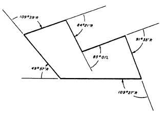
Figure 7-7.—Closed traverse by deflection-angle method.
Figure 7-7 shows a traverse in which one of the
deflection angles was turned to the lefft, all others to the
right. The sum of the right deflection angles is 444°59'.
Then, by subtracting the left deflection angle (85°01'),
you find that the angular error of closure is 02', which
is an average of 20" per deflection angle. This average
angular error of closure is then added to each right
deflection angle and subtracted from each left
deflection angle. After applying this adjustment to each
deflection angle in this example, you find, then, that the
sum of the adjusted angles to the right equals 445°00'40"
and that the sum of the left angles (of which there is only
one) is 85°00'40". The difference between these values
is 360°00'00", as it should be.
Remember that in adjusting the angles in a
deflection-angle traverse, you apply the adjustments to
right and left angles in opposite direction.
Adjusting for Linear Error of Closure
The procedure for distributing a linear error of
closure (one within the allowable maximum, of course)
over the directions and distances in a closed traverse is
called balancing or closing the traverse. Before you can
understand how to do this, you must have a knowledge
of latitude and departure.
LATITUDE AND DEPARTURE.— Latitude and
departure are values that are employed in the method
of locating a point horizontally by its plane coordinates.
In the plane coordinate system, a point of origin is
arbitrarily y selected for convenience. The location of a
point is given in terms of its distance north or south and
its distance east or west of the point of origin. The plane
coordinate system will be explained later in this chapter.
7-8