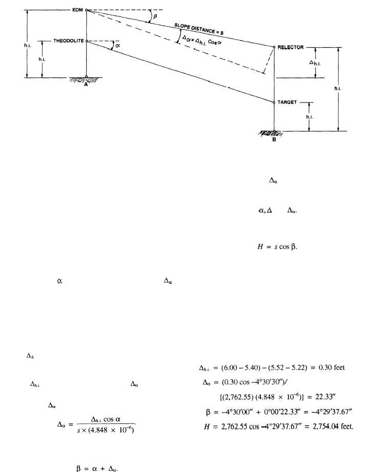
Figure 12-4.—Slope reduction using vertical angle and slope distance.
the theodolite, and the h.i. of the target. These differing
heights of the equipment must be considered in the
computations since they result in a correction that must
be applied to the observed vertical angle before the slope
distance can be reduced.
Figure 12-4 illustrates the situation in which the
slope distance and vertical angle are obtained from
separate setups of an EDM and a theodolite. In the
figure, the EDM transmitter, reflector, theodolite, and
target are each shown at their respective h.i. above the
ground. Angle a is the observed vertical angle and A. is
the correction that must be calculated to determine the
corrected vertical angle, ß, of the measured line. To
reduce the slope distance, s, we must first make
adjustment for the differing heights of the equipment.
This adjusted difference in instrument heights (Ah.i.) can
be calculated as follows:
&h.i.
= (h.i. reflector – h.i. target)
- (h.i. EDM - h.i. theodolite).
With Ah.i. known, you can now solve for that is needed
to determine the corrected vertical angle. You can
determine as follows:
Now, solve for corrected vertical angle, ß, by using the
formula:
NOTE: The sign of is a function of the sign of
the difference in h.i., which can be positive or negative.
You should exercise care in calculating ß so as to reflect
the proper sign of a, Ah.i. and .
Finally, you can reduce the slope distance, s, to the
horizontal distance, H, by using the following equation:
To understand how the above equations are used in
practice, let’s consider an example. Let’s assume that the
slope distance, s, from stations A to B (corrected for
meteorological conditions and EDM system constants)
is 2,762.55 feet. The EDM transmitter is 5.52 feet above
the ground, and the reflector is 6.00 feet above the
ground. The observed vertical angle is–4°30´00". The
theodolite and target are 5.22 feet and 5.40 feet above
the ground, respectively. Our job is to calculate the
horizontal distance. To solve this problem, we proceed
as follows:
The above example is typical of situations in which
the slope distance and the vertical angle are observed
using separate setups of an EDM and a theodolite over
the same station. Several models of the modern
12-4