and marked point when rays from A and B will give
a strong intersection (angle ADB is greater than 300).
First set up and level the plane table at point D
(first setup, fig. 9-4). Using plotted points a and b,
draw resection rays from A and B. These rays intersect
at d which is the tentative position of D. Draw a ray
from d’ toward C. Plot c’ on this line at the estimated
distance from D to C.
Next, set up the plane table at C (second setup, fig.
9-4) and orient by backlighting on D. Sight on A and
draw a ray through c’ intersecting line ad’ at a’. In a
like manner, sight on B to establish b’. You now have
a quadrilateral a’b’d’c’ that is similar to ABDC. Since,
in these similar quadrilaterals, line a’b’ should always
be parallel to line AB, the error in orientation is
indicated by the angle between ab and a’b’.
To correct the orientation, place the alidade on
line a’b’ and sight on a distinctive distant point. Then
move the alidade to line ab and rotate the table to sight
on the same distant point. The plane table is now
oriented, and resection lines from A and B through a
and b plot the position of point C.
THREE-POINT METHOD.— The three-point
method involves orienting the plane table and plotting
a station when three known plotted stations can be
seen but not conveniently occupied.
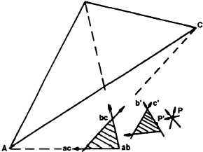
Set up the plane table at the unknown point P
(fig. 9-5) and approximately orient the table by eye or
compass. Draw rays to the known points A, B, and C.
The point ab denotes the intersection of the ray to A
with the ray to B. Points bc and ac are similar in their
notation. If the plane table is oriented properly, the
B
Figure 9-5.—Three-point method of resection.
three rays will intersect at a single point. Usually,
however, the first orientation is not accurate, and the
rays intersect at three points (ab, bc, and ac) forming
a triangle, known as the triangle of error.
From the geometry involved, the location of the
desired point, P, must fulfill the following three
conditions with respect to the triangle:
1. It will fall to the same side of all three rays; that
is, either to the right or to the left of all three rays.
2. It will be proportionately as far from each ray as
the distance from the triangle to the respective plotted
point.
3. It will be inside the triangle of error if the
triangle of error is inside of the main plotted triangle
and outside the triangle of error if it is outside the main
triangle.
In figure 9-5, notice that the triangle of error is
outside the main triangle, and almost twice as far from
B as from A, and about equally as far from C as from
B. The desired point, P, must be about equidistant
from the rays to B, and to C, and about one half as far
from the ray to A, and the three measurements must be
made to the same side of the respective rays. As drawn,
only one location will fulfill all these conditions and
that is near P’. This is assumed as the desired location.
The plane table is reoriented using P’ and back-
lighting on one of the farther points (B). The new rays
(a’, b’, and c’) are drawn. Another (smaller) triangle of
error results. This means that the selected position, P’,
was not quite far enough. Another point, P, is selected
using the above conditions, the table is reoriented, and
the new rays are drawn. If the tri- angle had become
larger, a mistake was made and the selected point was
on the wrong side of one of the rays. The directions
should be rechecked and the point reselected in the
proper direction.
The new point, P, shows no triangle of error when
the rays are drawn. It can be assumed to be the desired
location of the point over which the plane table is set.
In addition, the orientation is correct. Using a fourth
known and plotted point as a check, a ray drawn from
that point should also pass through P. If not, an error
has been made and the process must be repeated.
Normally the second or third try should bring the
triangle of error down to a point. If, after the third try,
the triangle has not decreased to a point, you should
draw a circular arc through one set of intersections (ab,
a’b’) and another arc through either of the other sets
(bc, b’c’, or ac, a’c’). The intersections of the two arcs
9-4