meridians as does the track of a vessel under a true
course. On the globe the parallels become shorter
toward the poles, and their length is proportionate to
the cosine of latitude. In the Mercator projection the
parallels are equally long. This means that any parallel
is increased by 1/cos
q,
or sec
q,
where
q
is the latitude
in degrees. To have the same scale along the parallels
as along the meridians, you must increase each degree
of latitude by the secant of the latitude. In this math-
ematical transformation, the tangent cylinder concept
was not employed, nor is it ever employed, in the
Mercator projection. A Mercator projection table is
used to plot the meridional distances. For intensive
study on elements of map projection, you may refer to
special publications published by the U.S. Coast and
Geodetic Survey that deal with this subject.
Universal Transverse Mercator Military Grid
An extensive application of the transverse
Mercator projection is in a grid reference system for
military maps called the universal transverse
Mercator (UTM) military grid system. In this
system a reference plane grid, like those used in our
state grid systems, is imposed on transverse Mercator
projections of relatively small areas. The basic
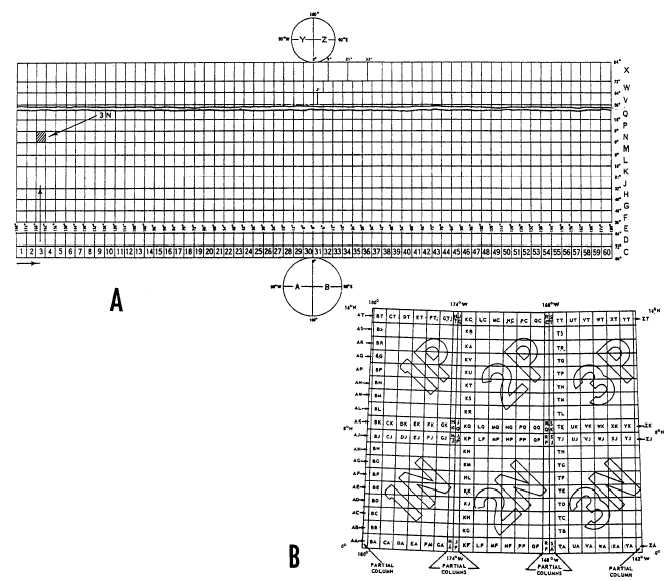
Figure 9-14.—(A) Grid zone designations of the military grid reference system; (B) 100,000-meter-square designations in the UTM
military grid system,
9-13