
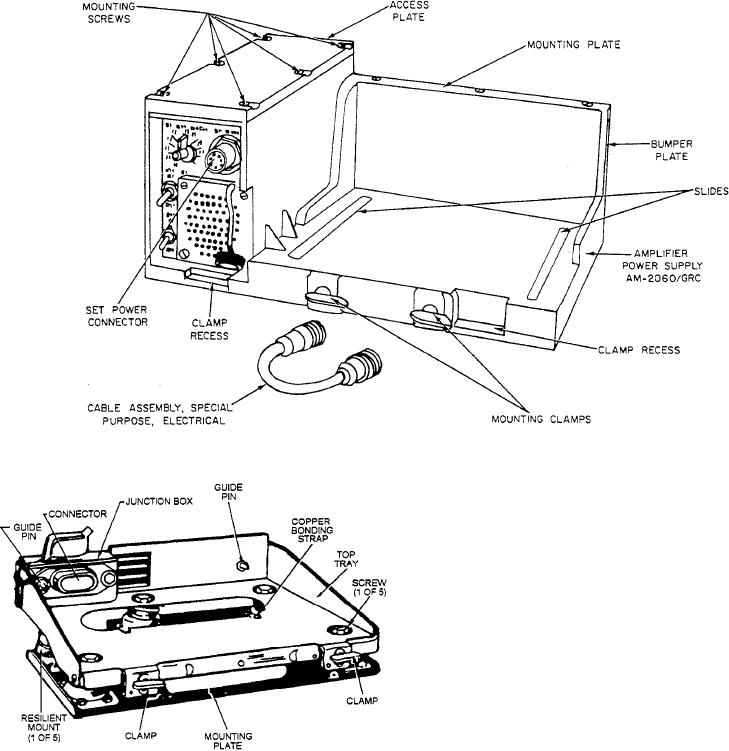
Figure 11-4B.--Amplifier AM-7060 for Radio Set AN/GRC-160.
4. Turn the band switch to the desired operating
frequency band.
5. Turn the MHz tuning and the kHz tuning
control knobs until the desired frequency
appears in the channel dial. (5A: REC-TRANS
FREQUENCY).
6. Set the antenna frequency control to match the
frequency appearing in the charnel dial (5A).
7. Turn the power switch to PWR ON.
8. Turn the speaker switch to SPKR ON.
9. Turn the volume control to 4.
10. Turn the function switch to ON.
Figure 11l-4C.--Mounting MT-1029/URC for Radio Set AN/
11. Press Handset H-189/GR (fig. 11-1)
GRC-160.
PUSH-TO-TALK switch (on the right side of
the handset) and speak into the handset.
To operate the radio, follow these steps. (The
Release the PUSH-TO-TALK switch to
numbers of Steps 1 through 10 below are keyed to the
LISTEN.
numbers on the diagram shown in figure 11-3.)
12. Adjust the VOLUME control (1 O) for a
1 Attach Cable CX-4665/GRC between the
desirable sound level.
power connectors (SET POWER).
13. To reduce the rushing noise when no signal is
2 Attach the antenna cable to the antenna
being received, turn switch (10) to SQUELCH.
connector (ANT).
Figures 11-4A, 11-4B, 11-4C, and 11-4D present the
3 Attach Handset H-189/GR (fig, 11-1) to either
components of the AN/GRC-160.
audio connector (AUDIO).
11-5

