
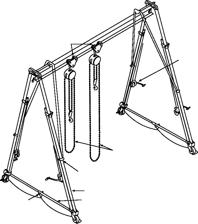
TROLLEYS
JACKS
(4)
MN020015
CHAIN HOISTS
S P R I N G - L O A D E D B O LT ( 4 )
TELESCOPE LEG (4)
QUICK-
SLIDING TUBE
RELEASE
PIN (2)
Figure 2-15.--Gantry A-frame.
Manual, NAVSEA AG-220BO-MRC-010. In addition
table assemblies are structured frame weldments with
folding leg weldments at each end that, after erection,
to these requirements, the stand must be tested anytime
are secured together with the center table assembly to
it is reassembled.
form one complete table assembly. The top of the table
assembly has two rows of industrial-type rollers and
RECOMMENDED READING LIST
stops at the ends of the completely assembled table.
The trays are also structural frame weldments with
NOTE: Although the following references were
rollers on top that support and permit a 360-degree
c u r r e n t w h e n t h i s N RT C wa s p u b l i s h e d , t h e i r
rotation of any bomb being assembled.
continued currency cannot be assured. When
consulting these references, keep in mind that they
Maintenance and testing of the stand must be
may have been revised to reflect new technology or
according to Periodic Maintenance Requirements
2-22

