
CO2 FLOODING SYSTEM
CO2 HOSE-AND-REEL SYSTEM
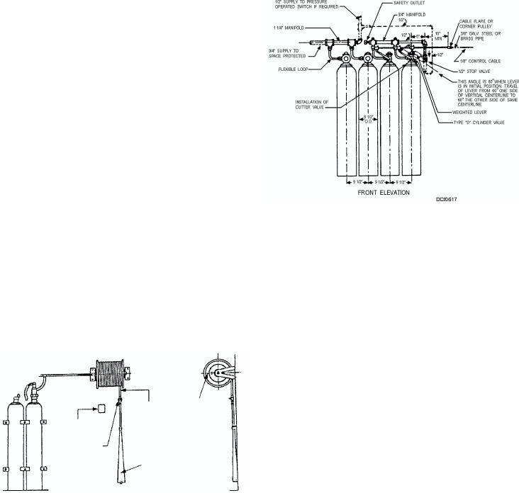
The CO2 flooding system (fig. 6-17) consists of
The CO2 hose-and-reel installation (fig. 6-16)
one or more cylinders connected by piping from the
consists of two cylinders, a length of special CO2 hose
valve outlets to a manifold. Fixed piping leads from the
coiled on a reel, and a horn-shaped nonconducting
manifold to various areas of the compartment to be
nozzle equipped with a second control valve. When the
f l o o d e d . C a b l e s r u n f r o m t h e va l ve c o n t r o l
hose and reel are both installed near the normal access,
mechanisms to pull boxes that are located outside the
each of the two cylinders may be actuated individually.
compartment containing the cylinders. (Sometimes,
Due to space limitations, cylinders may not be located
the cylinders are also located outside of the
near the hose reel. When the cylinders are more than
compartment to be protected.) To release CO2, just
10 feet from the hose reel, manual pull boxes are
break the glass in the front of the pull box and pull the
provided at the hose reel for discharging each cylinder
handle of the cable leading to the CO2 cylinders.
individually.
WARNING
Grooved nut discharge heads are to be
installed only for CO2 hose reel installations.
They must not be installed with CO2 total
flooding systems.
To operate a CO2 hose-and-reel system, you
should adhere to the procedure that include the steps as
follows:
1. Ensure the horn valve is in the CLOSED
position.
2. Open the control valve on the cylinder intended
for use.
3. Unreel the hose and run the horn to the point of
There are usually one or two valve control devices
attack on the fire.
in a CO2 flooding system. The number of valve control
4. Open the horn valve by turning the lever or by
devices provided will depend on the number of
depressing the squeeze grip.
cylinders in the bank. The remaining cylinders in the
bank (if any) are provided with pressure-actuated
5. Direct the CO2 discharge toward the base of the
discharge heads. These heads open automatically
fire.
when pressure from the controlled cylinders enters the
discharge head outlet.
Several manufacturers make various components
of the CO2 systems installed on naval ships. These
components differ in some minor details. Therefore,
for detailed information on a specific installation,
HOSE REEL
1/2" I.D.
GOOSE NECK
FLEXIBLE HOSE
always consult the appropriate manufacturer's
INSTRUCTION
technical manual.
PLATE
SHUTOFF VALVE
CAUTION
(NORMALLY CLOSED)
DISCHARGE
HORN
Before operating an installed CO2 system,
ensure all openings in the compartment are
DCf0616
closed and the ventilation system for the space
is secured. These precautions are necessary to
Figure 6-16. CO2 hose-and-reel system.
prevent the loss of CO2.
6-13