is
is
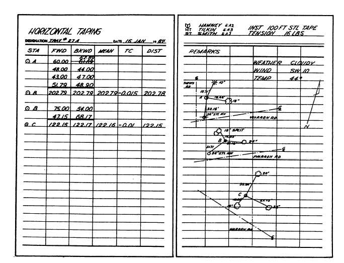
Figure AIII-3.—Horizontal taping.
the ground elevation at that point, the center number
Notes for a building layout are shown in figure
the rod reading, and the bottom number is the
AIII-15. Building corner numbers on the sketch must
perpendicular distance to the centerline. An additional
agree with the designation on the left-hand side of the
example of profile levels is shown in figure AIII-13.
notes. Grade rod setting is computed in the field. Batter
Slope-stake notes (fig. AIII-14), as with profile
elevations are entered in the first column on the
notes, are best recorded from the bottom to the top of
right-hand side of the notes—after having been
the page. As you see in the figure, in addition to grade
computed at the jobsite. The sketch must show all
rod, the right-hand page of the notes has left, center-line,
and right columns. In these columns the amount of cut
pertinent data for locating the building.
or fill, ground rod, and the distance of the slope stakes
Typical notes for a plane-table survey are shown in
from the center line are recorded for each station.
figure AIII-16.
AIII-3