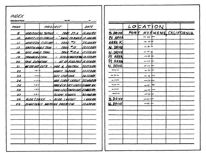
Figure AIII-2.—Index.
The set of horizontal angle control notes shown in
Differential leveling notes are shown in figure
figure AIII-8 indicates that the instrument was first set
up over station 0 + 00 and indexed on point No. 1. The
horizontal angle (to the right) to PI No. 1 was then
turned, as well as the horizontal angle to a church
steeple. This locates the traverse and ties it to a point that
will not be disturbed The instrument was then moved
to PI No. 1 and the deflection angle between 0 + 00 and
PI No. 2 was turned (twice), making sure that the angle
was recorded with its proper direction: right (R). The
instrument was then moved to PI No. 2 and the
procedures repeated
‘The set of horizontal taping notes in figure AIII-9
shows the proper way to tape and record distances
between points. The line in question is taped in both
directions, showing each distance and the mean
distance. The mean distance must be within 1 in 5,000,
or third-order accuracy. A good complete sketch is
required.
AIII-10. When making the page check do not add the
foresight for station 0 + 00, as it is a side shot. Also, note
that the stadia distance to 0 + 00 has been omitted for
the same reason. When making your sketch, you do not
need to show the backsight and foresight distances on
the sketch-only on the traverse points, and so forth,
normally found on a sketch.
Horizontal curve notes (fig. AIII-11) should include
all the curve data plus the deflection angles that are to
be turned during the layout of the curve. The sketch
should be as shown here. All stations that were staked
out should be shown and labeled on the sketch.
Profile and cross-section level notes (fig. AIII-12)
are best recorded from the bottom to the top of the page.
The left-hand side of the notes should contain columns
for stations, backsight (+), height of instrument (HI),
foresight (-), and elevations. The right side, as shown,
has left, center-line, and right columns. The top number
AIII-2


