Heavy steel tapes are repaired in a similar
manner, using the tape repair kit shown in chapter
11, figure 11-55.
MEASURING BY THE ELECTRONIC
DISTANCE-MEASURING SYSTEM
The electronic distance-measuring system is
now incorporated in various present-day surveying
practices, including traverse and triangulation
network. In traverse measurements, accurate
distances are directly measured in a straight
line and with minimum instrument setups. In
triangulation, the system is used to conduct base
line measurements that are precise enough to
maintain the accuracy of the survey.
In the electronic distance-measuring system,
the length of a linear interval is determined
by the use of equipment that (1) sends out
an electronic impulse of some sort, such as
a radar microwave or a modulated light wave,
and (2) measures the time required for the
impulse to travel the length of the interval.
The velocity or rate of travel of the impulse
is known. Therefore, once the time is also
known, the length of the linear interval can be
determined by applying the well-known equation
“distance = rate x time.”
Two types of electronic distance-measuring
devices (also called EDMs) commonly used
today are the MICROWAVE DEVICES and the
LIGHT WAVE DEVICES.
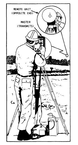
Figure 12-24.-Setting a microwave distance-measuring unit.
Measuring by Microwave Devices
The microwave distance-measuring device
(fig. 12-23) is an electronic instrument that
transmits precisely controlled RADIO WAVES
between two units. The waves are compared and
electronically changed into a visually readable
form from which the distance between the units
can be computed.
As shown in figure 12-24, the unit that
originates and transmits the modulated radio
waves is called the master. The unit at the opposite
end of the line from the master is known as the
remote. The two are identical instruments, each
being adaptable to use as either master or remote.
At the remote unit, the original transmission
is received, interpreted, and put on a new
carrier. This new modulation is amplified and
retransmitted to the master. The master analyzes
the new transmission and translates it into a trace
on a cathode ray tube that can be read visually.
The trace information is converted into a distance
based on the velocity of the radio waves. Because
this velocity is affected by atmospheric conditions,
corrections for temperature and barometric
pressure are applied according to instructions.
Each instrument is equipped with a shortwave
telephone set. By this means, the person at each
instrument can maintain communication with the
other. Details of the method of operating the
system must be learned from the manufacturer’s
instructions.
12-25