used. The NEC® also requires that the outside
edges of outlet and switch boxes without flush
plates NOT be recessed more than 1/4 in. below
the surface of the finished wall.
Receptacles
RECEPTACLES are used to plug in lights and
appliances around the building. Some of the types
of receptacle commonly used in interior wiring are
discussed in the following paragraphs in the order
of their frequency of use.
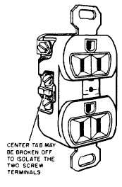
A CONVENIENCE OUTLET (fig. 9-18) is a
duplex receptacle with two vertical or T-slots and
a round contact for the ground. This ground is
connected to the frame of the receptacle and is
grounded to the box by way of screws that secure
the receptacle to the box.
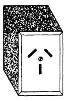
A RANGE RECEPTACLE (fig. 9-19) maybe
either a surface type or a flush type. It has two
slanted contacts and one vertical contact and is
rated at 50 A. Receptacles for clothes dryers are
similar but are rated at 30 A. Range and dryer
receptacles are rated at 250 V and are used with
three-wire, 115/230 V, two hot wires and a
neutral. A receptacle for use with an air-
conditioner taking 230 V is made with two
horizontal slots and one round contact for the
ground.
Also used in the Navy are strips that allow
movement of the receptacle to any desired
location. These strips are available in 3-ft and 6-ft
lengths and may even be used around the entire
room. This type of outlet is particularly desirable
in rooms where portable equipment or fixtures,
Figure 9-18.-A typical duplex convenience outlet.
Figure 9-19.-Range receptacle.
such as drafting tables and audio-visual
equipments, are used. Specialty outlets (weather-
proof are used in all exterior locations because
they resist weather damage.
Switches
For interior wiring, single-pole, three- or four-
way toggle switches are used. Most of the
switches will be single-pole, but occasionally a
three-way system is installed, and on rare
occasions, a four-way system.
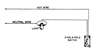
A single-pole switch (fig. 9-20) is a one-blade,
on-and-off switch that may be installed singly or
in multiples of two or more in the same metal box.
In a three-way switch circuit (fig. 9-21), there
are two positions, either of which may be used
to turn a light ON or OFF. The typical situation
is one in which one switch is at the head of a
stairway and the other at the foot.
A four-way switch (fig. 9-22) is an extension
of a three-way circuit by the addition of a four-
way switch series.
Figure 9-20.-Single-pole switch circuit.
9-14


