as the resistance increases, one must increase the
VOLTAGE, or ELECTROMOTIVE FORCE
(E), accordingly. The increase in voltage makes
it possible to use smaller wires or cables, thus
minimizing the support for aboveground
transmission lines, and consequently minimizing
the cost of the system.
U n d e r g r o u n d D i s t r i b u t i o n
The Navy uses UNDERGROUND power
distribution systems on most shore facilities for
several reasons: underground lines are secure
against damage that high winds and storms in-
flict on overhead lines in some areas; underground
lines leave clear areas and open spaces for the
operations of heavy mobile equipment; and
underground lines are much more secure against
enemy attack than overhead lines.
There are three principal categories of
underground lines: duct lines, cables buried
directly, and conduits located in tunnels. The
system most frequently installed by construction
battalions is the underground duct system, which
consists of manholes, handholes, duct lines, and
cables. In general, a representation of the system
layout and a list of materials needed to install the
system can be found in a standard set of drawings.
INTERIOR ELECTRICAL
WIRING SYSTEM
In general, the term service means the electrical
system that brings the power from the pole or
other point on the exterior power distribution line
to the point on or inside the building from which
it is distributed to the building circuits. Service
for a building consists of two parts: the service
conductors and the service equipment.
The SERVICE CONDUCTORS supply power
from the pole or other point on the exterior
distribution system to the building. These conduc-
tors may be SERVICE DROP conductors for
overhead service, or they may be SERVICE
LATERAL conductors for underground service.
From the service conductors, electrical power is
brought into the building through a SERVICE
ENTRANCE to the SERVICE EQUIPMENT on
or inside the building. The service equipment is
the necessary equipment, usually consisting of a
circuit breaker or switch or fuses, that is located
near the entry point of the supply conductors to
the building. This equipment is the main control
and means of cutting off the power supply to the
b u i l d i n g .
9-6
Service Conductors
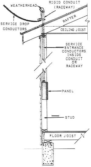
The SERIVCE DROP CONDUCTORS (fig.
9-8) run from the pole to the building. These
conductors may consist of an approved multi-
conductor cable or individual (single) conductor.
In either case, they must have thermoplastic,
rubber, or other weatherproof insulation. The
current-carrying capacity of the service drop
conductors must be sufficient to ensure that
ample current for the prospective maximum load
may be conducted without a temperature rise to
a point high enough to damage the insulation.
The NEC® specifies the minimum size conductors
that may be used for different load (amperage)
requirements.
Figure 9-9 shows an UNDERGROUND
SERVICE that brings power into a building. the
conductors, corresponding to the service drop that
Figure 9-8.—Overhead service entrance.


