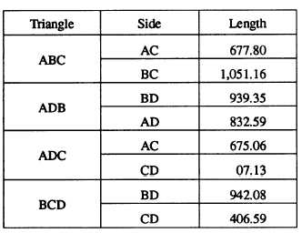
for AC and CD, and triangle BCD for BD and CD. The
solutions for each of the overlapping triangles are
summarized as follows:
secondary triangulation station is one that is sighted
from primary stations but is not itself used as an
instrument station. Only the primary stations are used to
extend the system of figures.
Each triangulation station must be marked in a way
that will make it visible from other stations from which
it is sighted. A mark of this kind is called a triangulation
signal. For a secondary station, the signal may be
relatively simple, such as a pole set in the ground or in
a pile of rocks, or a pole set on the ground and held erect
by guys. An object already in place, such as a flag pole,
a church spire, or a telegraph pole, will serve the
purpose. When the instrument itself must be elevated for
visibility, a tower is used.
Targets
As you can see, for each of the unknown sides of
the quadrilateral (AC, CD, and BD), values have been
obtained by two different routes. You can also see that
there are discrepancies in the values, almost the same
for AC and BD and smaller for CD. All the discrepancies
shown are much larger than would be tolerable in actual
practice; they reflect the high imprecision of the original
protractor measurement of the angles. The example has
been given here only to illustrate the basic principles and
procedures of chain-of-quadrilateral triangulation.
Later in this chapter you will see how observed angles
(measured in the field with the required precision) are
adjusted to ensure that values computed by different
routes will be practically close enough to each other to
satisfy precision requirements.
TRIANGULATION STATIONS, SIGNALS,
AND INSTRUMENT SUPPORTS
All triangulation stations of third order or higher
must be identified on the ground with a station marker,
at least two reference markers, and, if necessary, an
azimuth marker. These markers are usually embedded
in or etched on a standard station monument. Station
markers, monuments, and station referencing are
discussed in the EA3 TRAMAN. For low-order surveys,
unless otherwise required, the stations may be marked
with 2-inch by 2-inch wooden hubs.
A primary triangulation station is both a sighted
station and an instrument station; that is, it is a point
sighted from other stations and also a point where an
instrument is set up for sighting other stations. A
A target is generally considered to be a
nonilluminating signal. Target requirements can be met
by three general types—tripods, bipeds, and poles—all
of which may incorporate variations. The targets are
constructed of wood or metal framework with cloth
covers.
SIZE OF TARGET.— For a target to be easily
visible against both light and dark backgrounds, it
should be constructed in alternating belts of red and
white or red and yellow. For ready bisection, it should
be as narrow as possible without sacrificing distinctness.
A target that subtends an angle of 4 to 6 seconds of arc
will fulfill this purpose. Since 1 second of arc equals 0.5
centimeters at a 1-kilometer distance, an angle of 6
seconds requires a target 3 centimeters wide at 1
kilometer or 30 centimeters at 10 kilometers. Under
adverse lighting conditions, the target width will have
to be increased. Flags of an appropriate size may be
added to aid in finding the target. All cloth used on
targets should be slashed after construction to minimize
wind resistance.
TRIPOD TARGET.— The tripod target is the
most satisfactory from the standpoint of stability,
simplicity of construction, durability, and accuracy. It
ranges from a simple hood of cloth, cut and sewn into a
pyramid shape and slipped over the instrument tripod,
to the permanent tripod with the legs embedded in
concrete, sides braced, a vertical pole emplaced, and the
upper part boarded up and painted. Temporary tripod
targets may be constructed of 2-inch by 2-inch lumber,
pipes, poles, or bamboo joined at one end by wire or
bolts threaded through drilled holes. The tripod must be
15-27