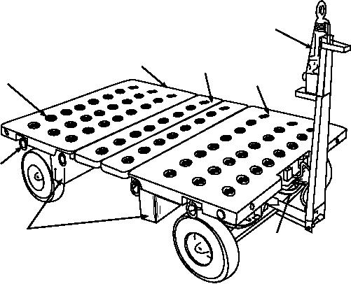
TOWBAR
HINGED
AFT DECK
DECK FORWARD
DECK
TIEDOWNS (64)
TIEDOWN
RINGS (8)
TOOL BOX, SIDE
HANDBRAKE
MN020014
Figure 2-14.--Aero 51B munitions trailer.
the insertion of ball-lock pins. The jacks are operated
an interconnecting electrical harness) are stored in
simultaneously to maintain the necessary length of the
toolboxes mounted underneath the forward and aft
legs of the A-frame at any given time, thereby ensuring
sections of the bed. The center section of the bed is
maximum gantry stability. When the A-frame is within
hinged and can be opened to provide a hatchway across
approximately 4 inches of its desired height, the
the full width of the trailer. Hinged bed panels have
ball-lock pins are removed, allowing the spring-loaded
double rails with holes at intervals to provide a
bolts to press against the telescoping legs. The
mounting base for chocks and roller adapters.
spring-loaded bolts snap into their respective locating
The Aero 51B trailer has a capacity of 8,500
holes when the desired height is reached.
pounds and can be towed in trains of not more than
Removal of a quick-release pin from the sliding
three. Maximum towing speed of one trailer is 20 miles
tube that forms the base of the A-frame permits the
per hour (mph); however, if more than one trailer is
frame to spread to any one of four positions.
being towed, the maximum speed is 10 mph.
Reinsertion of the quick-release pin maintains the tube
in a fixed position. The four 8-inch casters permit easy
GANTRY A-FRAME
maneuvering of the entire structure either indoors or
outdoors. The hoists can be positioned anywhere along
The gantry A-frame is used for suspending one
the desired height of the I-beam. The trolley wheels
portion of a mine when marrying to another. It has two
travel on its bottom flange.
trolleys and two air or chain hoists suspended from a
15-foot I-beam, supported at each end by a steel
The safe working load of the gantry A-frame, as
shown in figure 2-15, is either 3,000 or 4,000 pounds,
A-frame. The working height of the gantry is
d e p e n d i n g o n t h e h o i s t s u s e d . H ow ev e r, t h e
adjustable between approximate heights from 10 to 17
4,000-pound capacity must NEVER be exceeded.
feet by the operation of four independent
spring-loaded bolts and jacks attached to the A-frame
BOMB ASSEMBLY STAND
legs. The spring-loaded bolts seat into located holes in
the telescoping legs of the A-frame.
The bomb assembly stand provides a working
Adjusting the height of the A-frame requires first
height platform in magazine or bomb assembly areas
that each jack be wound tautly to assure support of each
upon which bombs of various weights and sizes can be
leg. Then the four spring-loaded bolts are pulled out of
assembled. The stand, as shown in figure 2-16, consists
of three table assemblies and four tray assemblies. The
their respective locating holes and held tensioned by
2-21

