CHAPTER 13
HORIZONTAL CONTROL
A system of control stations, local or
universal, must be established to locate the
positions of various points, objects, or details on
the surface of the earth. The relative positions of
detail points can be easily determined if these
points are TIED IN to a local control station; or,
if the control station is tied in to a geodetic
control, the positions of other detail points can
also be located relative to a worldwide control
system.
The main control system is formed by a tri-
angulation network supplemented by traverse. A
traverse that has been established and is used to
locate detail points and objects is often spoken
of as a CONTROL TRAVERSE. Any line from
which points and objects are located is a
CONTROL LINE. A survey is controlled horizon-
tally by measuring horizontal distances and
horizontal angles. This type of survey is often
referred to as HORIZONTAL CONTROL.
Horizontal control surveys are also conducted
to establish supplementary control stations for use
in construction surveys. Supplementary control
stations usually consist of one or more short
traverses run close to or across a construction area
to afford easy tie-ins for various projects. These
stations are established to the degree of accuracy
needed for the purpose of the survey.
In this chapter, we will identify common
procedures used in converting angular measure-
ments taken from a compass or transit survey,
recognize the methods used in establishing
horizontal control, and identify various field
procedures used in running a traverse survey.
DIRECTIONS AND DISTANCES
There are various ways of describing the
horizontal locations of a point, as mentioned in
chapter 12. In the final analysis, these ways are
all reducible to the basic method of description;
that is, by stating the length (distance) and direc-
tion of a straight line between the point whose
location is being described and a reference point.
Direction, like horizontal location itself, is also
relative; that is, the direction of a line can only
be stated relative to a REFERENCE LINE of
known (or sometimes of assumed) direction. In
true geographical direction, the reference line is
the meridian passing through the point where the
observer is located; and the direction of a line
passing through that point is described in terms
of the horizontal angle between that line and the
meridian. In magnetic geographical direction, the
reference line is the magnetic meridian instead of
the true meridian.
CONVERTING DIRECTIONS
The direction of a traverse line is commonly
given by bearing. In field traversing, however,
turning deflection angles with a transit is more
convenient than orienting each traverse line to a
meridian. The method of converting bearings to
deflection angles is explained in the following
paragraphs.
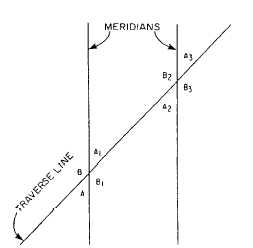
Converting Bearings to Deflection Angles
Converting bearings to deflection angles is
based on the well-known geometrical proposition
shown in figure 13-1.
Figure 13-1.-Parallel lines (meridians) intersected by a
traverse line, showing relationship of corresponding
angles.
13-1