be measured. Extend line AO on to C; extend line
BO on to D. When you set the center of the
protractor at O, make sure that both points c and
a are on line AC. Take your reading at point d
as well as at point b when you measure the angle.
If you are laying off the angle BOA, protract and
mark point d as well as point b; this gives you
three points (d, O, and b) for establishing line DB.
If you are using a semicircular protractor, you
can’t, of course, locate point d; but your accuracy
will be improved by lining up c, O, and a before
you measure or lay off the single angle BOA.
PARALLEL AND
PERPENDICULAR LINES
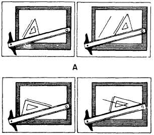
To draw a line parallel to a given line (fig. 3-6,
view A), adjust the hypotenuse of a triangle in
combination with a straightedge (T square or
triangle) to the given line; then, holding the
straightedge firmly in position, slip the triangle
to the desired position and draw the parallel line
along the hypotenuse.
To construct a line perpendicular to an existing
line,
use the triangle and straightedge in
combination, with the hypotenuse of the triangle
resting against the upper edge of the straightedge
(fig. 3-6, view B). Adjust one leg of the triangle
to a given line. Then slide the triangle along the
supporting straightedge to the desired position and
draw the line along the leg, perpendicular to the
Figure 3-6.-Drawing parallel and perpendicular lines.
leg that was adjusted to the given line. In the same
manner, angles with multiples of 15 degrees may
be drawn, using the triangle combinations shown
in figure 3-4.
CURVED LINES
Many drawings that you will prepare require
the construct ion of various curved lines. Basically
there are two types of curved lines: circles and
segments of circles, called arcs, which are drawn
with a compass; and noncircular curves, which
are usually drawn with french curves. In this
chapter we will discuss only techniques for using
the compass and the french curve. Application of
compass techniques in geometric construction will
be covered in chapter 4.
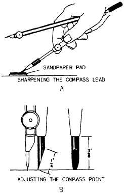
Use of the Compass
When you are drawing circles and arcs, it is
important that the lines produced with the
compass are the same weight as corresponding
pencil lines. Since you cannot exert as much
pressure on the compass as you can with
pencils, you should use a compass lead that is
Figure 3-7.-Sharpening the compass lead and adjusting the
point.
3-6