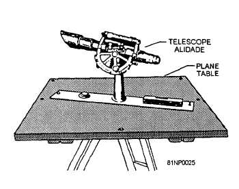
PLANE TABLE
When combined with the stadia board or
Philadelphia rod, the plane table are used in what is
generally known as plane table surveys. Which these
instruments, the direction, the distance, and the
difference in elevation can be measured and plotted
directly in the field. The plane table opration produces
a completed sketch or map manuscript without the need
for further plotting or computing.
A plane table (fig. 11-29) consists of a drawing
board mounted on a tripod with a leveling device
designed as part of the board and tripod. The commonly
used leveling head is the ball-and-socket type. The
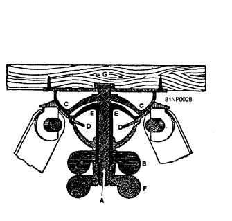
cross section of a plane table with the tripod head is
shown in figure 11-30. The board (G) usually is either
18 by 24 in. or 24 by 31 in. and has an attached recessed
fitting that screws onto the top of the spindle (A). A
wingnut (B) controls the grip of parts C and D on cup
E. By releasing the wingnut (B), you can tilt the
drawing board in any direction to level it. Another
wingnut (F) acts only on the spindle and, when released,
permits the leveled board to be rotated on azimuth for
orientation. The tripod is shorter than the transit or level
tripods and, when set up, brings the plane table about
waist high for easy plotting. One precaution must be
observed in attaching the plane table to the tripod head.
A paper gasket should be placed between the fittings to
prevent sticking or “freezing” of the threads.
The plane table is setup over a point on the ground
whose position has been previously plotted, or will be
Figure 11-29.-Plane table.
Figure 11-30.-Cross section of a plane table tripod bead.
plotted, on the plane table sheet during the operation.
The board is oriented either by using a magnetic
compass for north-south orientation or by sighting on
another visible point whose position is plotted. The
board is clamped and the alidade is pointed toward any
new, desired point using the plotted position of the setup
ground station as a pivot. A line drawn along the
straightedge that is parallel to the line of sight will give
the plotted direction from the setup point to the desired
point. Once the distance between the points is
determined, it is plotted along the line to the specified
scale. The plotted position represents the new point at
the correct distance and direction from the original
point. By holding the plane table orientation and
pivoting the alidade around the setup point, you can
quickly draw the direction to any number of visible
points. The distance to these points is determined by
any conventional method that meets the requirements
for the desired accuracy and can be plotted along their
respective rays from the setup point. Thus, from one
setup, the positions of a whole series of points can be
established quickly. For mapping, the difference in
elevation is also determined and plotted for each point.
The map is completed by subdividing the distances
between points with the correct number of contours
spaced to represent the slope of the ground.
11-33