drainage system; however, there are other features,
such as drainage ditches. Both storm sewers and
ditches carry surface runoff. The only real difference
between a drainage ditch and a storm sewer is the fact
that the ditch lies on the surface and the storm sewer
lies below the surface.
Similarly, there is no essential difference in
mechanical principle between an artificial and a
natural drainage system. Like a natural channel, an
artificial channel must slope downward and must
become progressively larger as it proceeds along its
course, picking up more runoff as it goes. Like a
natural system, an artificial system must reach a
disposal point—usually a stream whose ultimate
destination is the sea or a standing inland body of
water. At the terminal point of the system where the
accumulated runoff discharges into the disposal point,
the runoff itself is technically known as discharge.
The discharge point in the system is called the outfall.
Ditches.— A surface drainage system consists
principally of ditches that form the drainage channels.
A ditch may consist simply of a depression formed in
the natural soil, or it may be a paved ditch. Where a
ditch must pass under a structure (such as a highway
embankment, for example), an opening called a
culvert is constructed. A pipe culvert has a circular
opening; a box culvert has a rectangular opening.
Walls constructed at the ends of a culvert are called
end walls. An end wall, running perpendicular to the
line through the culvert, may have extensions called
wings (or wing walls), running at an oblique angle to
the line through the culvert.
Storm Sewers. —An underground drainage
system (that is, a storm sewer) consists, broadly
speaking, of a buried pipeline called the trunk or
main, and a series of storm water inlets, which admit
surface runoff into the pipeline. An inlet consists of a
surface opening that admits the surface water runoff
and an inner chamber called a box (sometimes called
a catch basin). A box is usually rectangular but may
be cylindrical. An inlet with a surface opening in the
side of a curb is called a curb inlet. A working drawing
of a curb inlet is shown in figure 10-1. An inlet with a
horizontal surface opening covered by a grating is
called a grate (sometimes a drop) inlet. A general
term applied in some areas to an inlet that is neither a
curb nor a grate inlet is yard inlet.
Appurtenances. —Technically speaking, the
term storm sewer applies to the pipeline; the inlets are
called appurtenances. There are other appurtenances,
the most common of which are manholes and
junction boxes. A manhole is a box that is installed,
of necessity, at a point where the trunk changes direc-
tion, gradient, or both. The term manhole originally
related to the access opening at one of these points;
however, a curb inlet and a junction box nearly always
have a similar access opening for cleaning, inspection,
and maintenance purposes. One of these openings is
often called a manhole, regardless of where it is
located. However, strictly speaking, the access
opening on a curb inlet should be called a curb-inlet
opening; and on a junction box, a junction-box
opening. Distances between manholes are normally
300 feet, but this distance may be extended to a
maximum of 500 feet when specified.
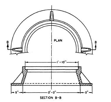
The access opening for a manhole, curb inlet, or
junction box consists of the cover and a supporting
metal frame. A frame for a circular cover is shown in
figure 10-2. Some covers are rectangular. The frame
usually rests on one or more courses of adjusting
blocks so that the rim elevation of the cover can be
varied slightly to fit the surface grade elevation by
varying the vertical dimensions, or the number of
courses, of the adjusting blocks.
A junction box is similar to a manhole but is
installed, of necessity, at a point where two or more
trunk lines converge. The walls of an inlet, manhole,
or junction box maybe constructed of special concrete
masonry units or of cast-in-place concrete. The
bottom consists of a formed slab, sloped in the
Figure 10-2.—Frame for an access opening.
10-5