determine the area of sections of this kind, you should
use a method of determining area by coordinates.
For explanation purpose, let’s consider station 305
(fig. 10-6). First, consider the point where the center
line intersects the grade line as the point of origin for
the coordinates. Vertical distances above the grade line
are positive Y coordinates; vertical distances below the
grade line are negative Y coordinates. A point on the
grade line itself has a Y coordinate of 0. Similarly,
horizontal distances to the right of the center line are
positive X coordinates; distances to the left of the center
line are negative X coordinates; and any point on the
center line itself has an X coordinate of 0.
Plot the cross section, as shown in figure 10-7, and
be sure that the X and Y coordinates have their proper
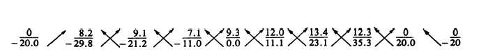
signs. Then, starting at a particular point and going
successively in a clockwise direction, write down the
coordinates, as shown in figure 10-8.
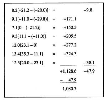
After writing down the coordinates, you then mul-
tiply each upper term by the algebraic difference of
the following lower term and the preceding lower term,
as indicated by the direction of the arrows (fig. 10-8).
The algebraic sum of the resulting products is the
double area of the cross section. Proceed with the
computation as follows:
Since the result (1,080.70 square feet) represents
the double area, the area of the cross section is one
half of that amount, or 540.35 square feet.
By similar method, the area of the cross section at
station 306 (fig. 10-7) is 408.40 square feet.
EARTHWORK VOLUME.— As discussed
previously, when you know the area of two cross
sections, you can multiply the average of those
cross-sectional areas by the known distance between
them to obtain the volume of earth to be cut or filled.
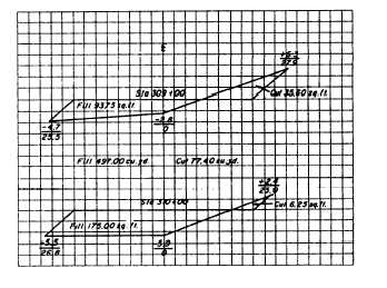
Consider figure 10-9 that shows the plotted cross
sections of two sidehill sections. For this figure, when
you multiply the average-end area (in fill) and the
average-end area (in cut) by the distance between the
two stations (100 feet), you obtain the estimated
amount of cut and fill between the stations. In this
case, the amount of space that requires filling is
computed to be approximately 497.00 cubic yards and
the amount of cut is about 77.40 cubic yards.
MASS DIAGRAMS.— A concern of the highway
designer is economy on earthwork. He wants to know
exactly where, how far, and how much earth to move
in a section of road. The ideal situation is to balance
the cut and fill and limit the haul distance. A technique
for balancing cut and fill and determining the
Figure 10-9.—Plots of two sidehill sections.
Figure 10-8.—Coordinates for cross-section station 305 shown in figure 10-7.
10-10