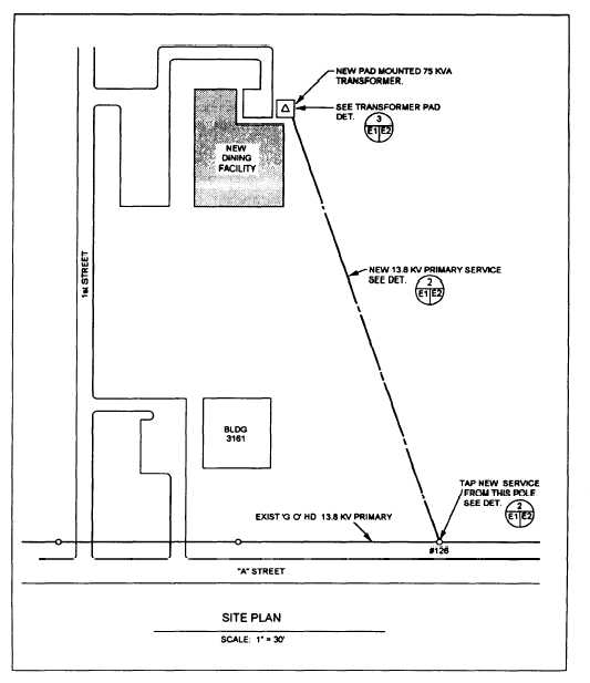
Figure 2-15.—Electrical site plan.
Figure 2-15 shows a simple electrical site plan. This
plan shows the routing of a new 13.8-kilovolt (kV)
primary service line to a new dining facility. The new
service is tapped to an existing 13.8-kV overhead
primary feeder, runs down existing pole Number 126,
and then runs underground to a new pad-mounted
75-kilovoltampere (kVA) transformer located next to
the new facility.
Although a competent Construction Electrician or
contractor could install this new service line from only
the site plan, as shown in figure 2-15, he would have to
prepare additional drawings or sketches to show his
workmen the specific details of the construction.
Therefore, to provide a better description of the
installation, the electrical designer prepares additional
electrical details.
Electrical Details
The purpose of details is to leave little doubt about
the exact requirements of a construction job. In pre-
paring the details for the installation shown in figure
2-15, the designer chose to begin at the existing pole and
work towards the new transformer pad. Figure 2-16 is a
detail of the existing pole. This detail leaves little doubt
about the requirements at the pole. For example, it
shows the existing pole, crossarm, the existing 13.8-kV
feeder, and required clearance distances. It also shows
that the new circuit taps the existing conductors and then
2-12