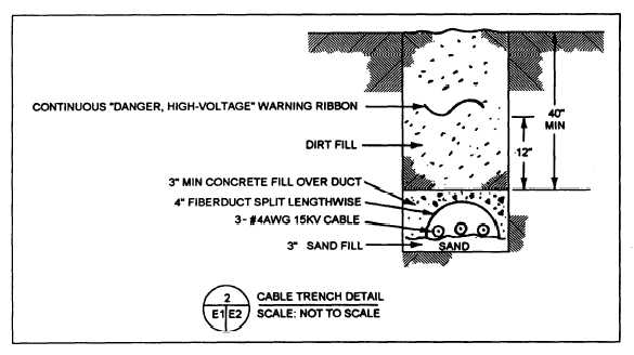
Figure 2-17.—Cable-trench detail for use with the site plan shown in Figure 2-15.
runs to three new 10-ampere fused cutouts before
running to the new cable terminals and lightning
arresters.
Figure 2-16 also shows that a new three-wire
shielded cable is connected to the cable terminators
and runs down the pole. From the pole, the cable is
then run, as shown in figure 2-17, at a specified
distance underground to the new transformer pad.
Figure 2-18 is a detail of the pad that the designer
included in the working drawings for the circuit
installation. As you can see, these details leave little
doubt about the job requirements. However, other
information, such as specified material requirements
for the concrete, cables, conduit, and so forth;
specified procedures for backfilling the trench and
placing the concrete; and any other information
necessary to a fill understanding of the material and
installation requirements should also be shown on the
drawings or in the project specifications.
The preceding discussions of electrical trans-
mission and distribution systems, distribution plans, and
electrical details should leave you in a better position to
aid the engineering officer or other design engineers.
However, to increase your knowledge and to become
even more valuable as an EA, you should further your
studies by reading other publications, including the CE
TRAMANs and commercial publications, such as The
Lineman’s and Cableman’s Handbook by Kurtz and
Shoemaker.
Now let us look at some other utility systems that
you will be involved with.
WATER SUPPLY AND DISTRIBUTION
A water supply system consists of all the facilities,
equipment, and piping that are used to obtain, treat, and
transport water for a water distribution system. A
distribution system is a combination of connected pipes
that carry the supplied water to the users. In this section,
we will discuss water distribution so you will be familiar
with the elements of a distribution system and types of
information that is required on distribution drawings.
First,, however, we will discuss water sources and the
need for water treatment. Although it is the engineer’s
responsibility to select a water source for use, to
determine the methods of developing the source, and to
design the supply and distribution system, you should
have a general knowledge of this subject so you, as a
technician, will be better able to assist the engineer.
WATER SOURCES AND TREATMENT
While the Navy prefers to obtain potable water from
nearby public sources, it is sometimes not possible to do
so. The following text briefly discusses the different
types of water sources, source selection and develop
ment, and the need for water treatment.
Water Sources
For most uses, the principal source of water is rain.
This source is classified as surface water and ground-
water.
2-14