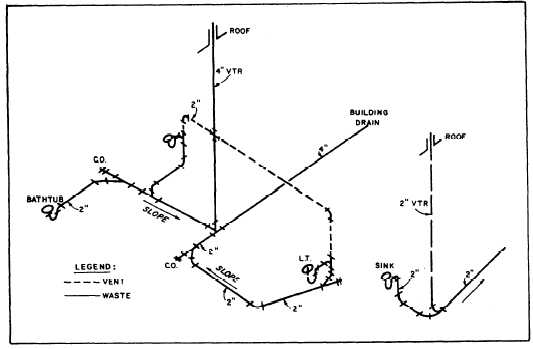
Figure 4-2.—Riser diagram for waste and soil piping.
needed to install the plumbing system. As the
complexity of the building plumbing increases,
however, your ability to describe the plumbing layout
accurately and clearly using only a plumbing plan
diminishes. This can easily lead to misinterpretations by
the users of the plan. In such cases as this, it is common
practice to supplement the plumbing plan with riser
diagrams.
The most commonly used type of riser diagram for
plumbing is the isometric riser diagram. As you see in
the examples shown in figures 4-1 and 4-2, the isometric
riser diagram provides a three-dimensional
representation of the plumbing system. Although a riser
diagram is usually not drawn to scale, it should be
correctly proportioned. In other words, a long run of
piping in the plumbing plan should be shown as a long
run of piping in the riser diagram. Conversely, short runs
should be shown as short runs. Make sure, too, that you
use proper symbols (from MIL-STD-17B) for the
piping and fittings. This makes it easy for someone
familiar with the symbols to read and interpret the
drawing. A glance at figure 4-1 tells you, for example,
that the plumbing system contains three gate valves and
that all of the fittings are screw-type fittings. Be sure that
the pipe sizes are properly labeled, especially where
changes in pipe size occur. Label all fixture connections
to identify to what fixture the piping connects. In figure
4-1, the fixtures are spelled out; however, it is also
common practice to label the fixtures using an
alphanumeric coding, keyed to a fixture schedule.
Another type of riser diagram, though less often
used in construction drawings, is the orthographic riser
diagram that shows the plumbing system in elevation.
When used, it is normally reserved for buildings that are
two or more stories in height. Also, since you probably
cannot clearly describe an entire plumbing system for a
building in a single elevation, more than one
orthographic riser diagram is necessary for the building.
Examples of these diagrams can be found in
Architectural Graphic Standards, by Ramsey and
Sleeper.
ELECTRICAL DIVISION
Included in the electrical section are power and
lighting plans, electrical diagrams, details, and
schedules. Chapters 9 and 10 of the EA3 TRAMAN
provide a discussion of interior wiring materials and the
drawing of electrical plans.
Electrical single-line block diagrams are drawings
that show electrical components and their related
connections in a diagrammatic form. The diagrams,
seldom drawn to scale, use standard symbols to
represent individual pieces of electrical equipment and
lines to represent the conductors or wires connecting the
equipment.
4-3