Figure 4-1.—Hot- and cold-water riser diagram.
Show the location and direction of all new utilities,
of all materials, such as concrete and reinforcing steel.
unless separate utility site plans are included in other
divisions, such as the mechanical, plumbing, or
electrical divisions. That is sometimes done for large,
complex projects.
ARCHITECTURAL DIVIS1ON
The architectural division includes drawings, such
as floor and roof plans, interior and exterior elevations,
millwork, door and window schedules, finish schedules,
special architectural treatments, and nonstructural
sections and details. For a discussion of these drawings,
you should review chapter 10 of the EA3 TRAMAN.
STRUCTURAL DIVISION
The structural division is comprised of all of the
drawings that fully describe the structural composition
and integrity of a building or structure. Included in the
division are the foundation plan and details; floor, wall,
and roof framing plans and details; reinforcing plans and
details; beam and column details; and other such
structural plans and details. In a set of drawings, the first
sheet in the structural division also should include, when
applicable, roof, floor, wind, seismic, and other loads,
allowable soil bearing capacity, and allowable stresses
Again, you should review chapter 10 of the EA3
TRAMAN.
MECHANICAL DIVISION
The mechanical division includes the plans, details,
and schedules that describe the heating, ventilating, and
air-conditioning (HVAC) systems equipment and
installation requirements. We’ll discuss more about
these systems later in this chapter.
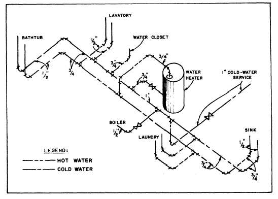
The mechanical division also includes plumbing
drawings that show the fixtures, water supply and waste
disposal piping, and related equipment that are to be
installed in a building. The drawings include plumbing
plans, riser diagrams, details, and fixture schedules.
Remember, that in the order of drawings, plumbing
drawings always follow the HVAC drawings.
As you recall from your study of chapters 8 and 10
of the EA3 TRAMAN, a plumbing plan (or layout) is a
plan view of the fixtures, lines, and fittings to be
installed in a building. For an uncomplicated building
containing, let’s say, one water closet and one lavatory,
you can easily prepare a plumbing plan that can be
clearly interpreted by the planners and estimators,
inspectors, or other users of the drawing. For such a
building, the plumbing plan might well be all that is
4-2