Piles.— You may be required to position piles,
record pile-driving data and mark piles for cutoff.
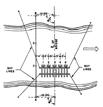
Figure 10-18 shows points A and B established as a
reference line 10 feet from the center line of a bridge.
Stretch a wire rope between points A and B with a piece
of tape or a wire rope clip at each pile-bent position
(such as C or D).
Locate the upstream pile (pile No. 1) by measuring
an offset of 4 feet from the line AB at C. A template is
then floated into position and nailed to pile No. 1 after
it is driven. The rest of the piles are positioned by the
template.
If it is impractical to stretch a wire rope to the far
shore, set up a transit at a convenient distance from the
center line of the bridge. Position the piles by sighting
on a mark located the same distance from the center line
of the template. Before driving piles, you must measure
the length of piles. Measure the distance between the
piles by chaining.
During pile driving, keep a complete record of the
following: location and number of piles, dimensions,
kind of woods, total penetration, average drop of
hammer, average penetration under last five blows,
penetration under last blow, and amount of cutoff.
Mark elevations on the two end piles by nailing two
3- by 12-inch planks to guide the saw in cutting the
piles to the specified height.
BRIDGE GRADE STAKES.— Elevations are
taken from bench marks set in, or near, the
Figure 10-18.—Method of positioning piles.
construction area. Consider permanency, accessibil-
ity, and convenience when setting bench marks. Set
grade stakes for a bridge site in the same manner as
the grade stakes on any route survey. Make sure that
the senior petty officer in charge of the job has suf-
ficient information so that the exact method being
used to designate the grade can be understood.
Sewer Stakeout
To stake out a sewer, you obtain data from a plan
and profile that shows (1) the horizontal location of each
line in the system, (2) the horizontal location and char-
acter of each manhole, (3) the invert elevations at each
manhole, and (4) the gradient of each line. You will also
have detail drawings of each type of appurtenance. If
manholes in the same category are of different types,
you may identify them by letter symbol, as CI “A,” and
so on. In addition, identification of a particular appur-
tenance may be by consecutive number, as CI “A” #3.
The stakeout consists of setting hubs and stakes to
mark the alignment and indicate the depth of the sewer.
The alignment may be marked by a row of offset hubs
and stakes or by both offset hubs and a row of center-
line stakes. Cuts may be shown on cut sheets (also called
grade sheets or construction sheets) or may be marked
on the stakes, or both. The cuts shown on the center-line
stakes guide the backhoe operator or ditcher operator;
they are usually shown to tenths; they generally repre-
sent the cut from the surface of the existing ground to
the bottom of the trench, taking into account the depth
to the invert, the barrel thickness, and the depth of any
sand or gravel bed. The cuts marked on the stakes next
to the hubs are generally shown to hundredths and
usually represent the distance from the top of the hub to
the invert; these cuts guide the pipe crew. The use of
these cuts in transferring the information to batter
boards or various types of offset string lines was de-
scribed in chapter 14 of the EA3 TRAMAN.
If the survey party stakes only the offset hubs, then
the construction crew usually sets center-line stakes for
line only and uses the hubs as a guide for the depth of
excavation. The extent of the stakeout and computa-
tions performed by the survey party and the correspond-
ing extent of such work done by the construction crew
depend on the capabilities and the availability of per-
sonnel and the work load. In any case, hubs and/or
stakes are generally set at 25-foot intervals, though
50-foot and even 100-foot intervals have been known
to suffice.
Sewer hubs are usually offset from 5 to 8 feet from
the center line. Before you enter the field, you
compute from the profile the invert elevation at every
10-19