
Figure 2-60.--Inserting the drive spring.
and the bolt into the receiver until the end of the
operating rod is even with the rear of the receiver. Insert
the drive spring guide into the drive spring; then insert
the opposite end of the drive spring into the recess of the
operating rod, as shown in figure 2-60. Pull the trigger
and push in the drive spring until the head of the guide is
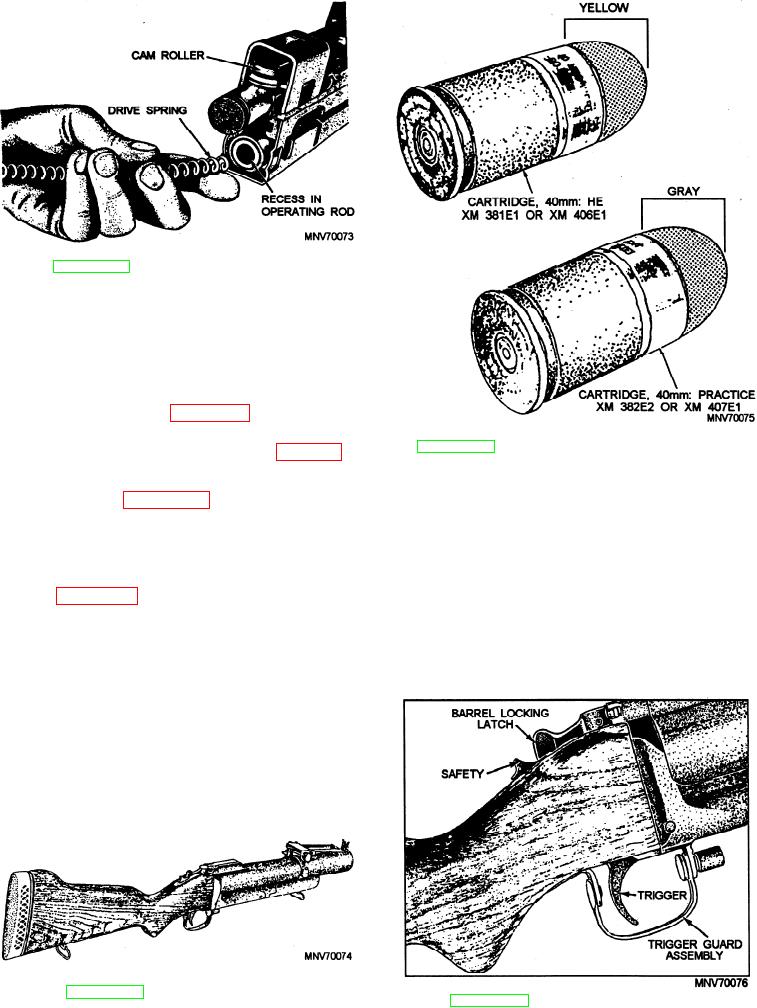
Figure 2-62.--Cartridges used with the M79 grenade
approximately one inch from the receiver (fig. 2-56).
launcher.
4. Insert the buffer plunger into the drive spring
guide, as shown in figure 2-56. Push forward on the
buffer until the operating rod and the bolt go fully
forward. Push in on the buffer until the recesses on the
NOTE
buffer are aligned with the recesses in the receiver.
Replace the buffer yoke from the top of the receiver, as
The bolt must be in the rear (cocked)
shown in figure 2-55.
position before you can close the cover.
5. Align the guide rails of the stock with the guide
For further information on the M60 machine gun,
rails on the receiver. Push forward until the stock is
refer to the Army's TM 9-1005-224-24 and TM 9-1005-
fully seated. You will hear a distinct click when the
24-10.
latch engages.
6. To check for correct assembly, pull the cocking
handle to the rear and return it to its forward position.
Close the cover and pull the trigger. The bolt should go
forward.
Figure 2-61.--M79 grenade launcher.
Figure 2-63.--Grenade launcher controls.
2-32