unit is maintained according to the Planned
foreign matter into the transfer unit or into the cylinder
Maintenance System (PMS) and with the
being recharged. Do not open the supply cylinder valve.
manufacturer's instructions.
Step 3. Place the empty cylinder on the scale. If a
rack is used, invert the cylinder in a near vertical
RACK FOR
position; otherwise set it horizontally.
INVERTING
PORTABLES
Step 4. Connect the pump outlet hose to the
PORTABLE 15 LB
CYLINDER BEING
STANDARD
recharging adapter. The pump outlet hose is fitted with a
RECHARGED
COMMERCIAL
50 LB CYLINDER
shutoff valve. Check all connections to ensure that they
are correct and secure. All connections should be made
with a wrench, using a slow, steady pulling motion. Do
not jerk the wrench and do not hit it with a hammer.
Step 5. After making certain that the shutoff
valve in the pump outlet hose is tightly closed and the
SCALES
valve of the cylinder to be recharged is in the OPEN
position, completely open the valve of the supply
cylinder.
MOTOR-DRIVEN
PUMP
TILTING
Step 6. Balance the scale and note the weight of
RACK
the cylinder being recharged. When using beam-type
DCf0504
scales, set the scale to the weight of the empty cylinder
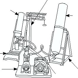
Figure 5-4. CO2 transfer unit.
plus the desired charge.
Step 7. Open the shutoff valve in the pump outlet
As a Damage Controlman, you may be required to
hose and allow the CO2 in the supply cylinder to flow
clean, inspect, and lubricate the CO2 transfer unit. You
under its own pressure into the cylinder being
may also be involved in replacing components of the
recharged.
unit, testing as required, and in recharging CO2 bottles.
Step 8. When the weight of the cylinder being
Before operating the CO2 transfer unit, you must
recharged stops increasing, the CO2 has stopped
ensure the switch on the side of the motor is in the OFF
flowing under its own pressure. At this point, start the
position. Check the circuit from which the motor is to
transfer unit and watch the scale carefully. The transfer
pump should be started only when all valves are verified
be energized and make certain it is the same as that
correctly aligned; otherwise, overpressurization in the
indicated in the nameplate on top of the motor. If a
transfer system may rupture the neoprene seal.
220-volt, 60-cycle, single-phase current is available,
the hookup of the motor leads should be arranged so
CAUTION
the motor will operate in this circuit. A wiring diagram
for operation on 220 volts is located on the motor
Do not close the valve of the cylinder
nameplate. Check all CO2 connections on both the
being recharged or the shutoff valve in the
inlet hose and outlet hose. (The 6-foot-long hose is the
pump outlet hose while the transfer unit is
pumping.
pump outlet hose.) Make certain that all connections
between the fittings are tight. This is very important,
Step 9. When the full capacity of the cylinder
because the CO2 is stored under high pressure.
being recharged has been reached, perform the
The steps of the procedure you should adhere to
following operations in rapid succession.
when operating the CO2 transfer unit are as follows:
a.
Stop the transfer unit motor.
Step 1. With the transfer unit, scale, and tilt racks
b. Tightly close the shutoff valve in the
in place, check the supply cylinder. Use only the
pump outlet hose.
50-pound commercial cylinders. The cylinder shall be
c.
Close the valve of the cylinder being
inverted.
recharged.
Step 2. Connect the pump inlet hose to the supply
Step 10. Disconnect the hose from the cylinder
cylinder outlet. The connection adapter of the hose is
being recharged. Do this very slowly to allow the escape
fitted with a screen to prevent the entrance of any
5-4

