On small ships, bulkhead terminals provide for a
NOTE
single horizontal run of portable cable along the
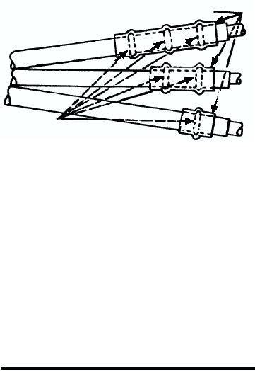
A new method of phase identification is
main deck, inside the superstructure. On large
similar to the old method, except that O rings
ships, there are generally terminals for two
a n d h e a t s h r i n k a b l e t u b i n g h ave b e e n
horizontal runs, one port and one starboard.
substituted for the cotton cord servings, as
These runs are located on the second deck. The
shown in figure 8-28.
terminals extend through the bulkhead and
project from it on both sides. They do not impair
HEAT SHRINKABLE TUBING
the watertight integrity of the ship. The cable
ends are inserted around the outer rim (or curved
surface) of the terminal into the holes provided.
There are three groups of three holes each. The
face of the terminal also contains three groups of
three holes each. The square-shanked insulated
wrenches fit into these holes and are used to
secure the cable in the terminal. Two of these
O RINGS
wrenches are provided in a rack mounted on the
DCf0828
bulkhead at each point where they are required.
Figure 8-28. New method of cable identification.
They must be kept in the rack at all times except
when they are actually in use.
Each lead and its corresponding position in the
R i s e r t e r m i n a l s a r e s i m i l a r t o bu l k h e a d
terminal can be identified by merely feeling the leads
terminals. However, they are connected to other
and matching the number of pieces of twine on each
riser terminals by permanently installed armored
lead with the same number of raised knobs in the
cable to provide vertical runs. These riser
proper area of the terminal. In older ships, the casualty
terminals carry the casualty power from the
power fittings have identifying V-shaped notches in the
generators to the main and the second deck
outer edge of the fittings instead of the knobs.
levels.
When connecting a casualty power cable run,
Portable switches are sometimes mounted on
remember that you must ALWAYS connect from the
bulkheads near the cable racks. These are simply
load to the source of supply. This is to avoid working
ON-OFF switches that are equipped with special
with live cables.
holes for use with the portable cables.
REVIEW QUESTIONS
The faces of the casualty power terminals of an ac
system are marked A, B, and C, and the ends of the
cables are colored black, white, and red, respectively.
Q20.
When casualty power cables are rigged, the
When connecting the cables to the terminals, connect
connections must always be made from the
the black lead to A, the white lead to B, and the red
load to the supply to avoid handling energized
lead to C.
cables.
The color code is not sufficient for making proper
1.
True
connections in the dark or under other adverse
conditions. Therefore, it is necessary to provide some
2.
False
means to identify each lead and its proper hole in the
terminal by touch. This is accomplished by molded
Q21.
Which of the following machinery can NOT
knobs in the A, B, and C portions of the terminals. There
be supplied by the casualty power system?
are one, two, or three knobs, respectively, in the A, B,
1.
Steering gear
and C portions of the terminals. Similarly, a piece of
2.
IC switchboards
heavy twine is placed on the black lead of the portable
cables, two pieces are placed on the white lead, and
3.
Fire pumps
three pieces are placed on the red lead. Each of these
4.
Main boiler plants
servings of twine is about one-half of an inch wide.
8-22

