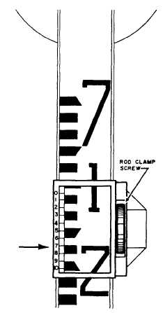
Figure 14-10.-Reading of 7.107 ft on back of Philadelphia
rod as indicated by arrow.
the rodman reads the target vernier, shown in the
same figure.
The reading to the nearest 0.01 ft is indicated
by the zero on the vernier. In figure 14-9, the
vernier zero indicates a reading of a few
thousandths of a foot more than 5.84 ft. To
determine how many thousandths over 5.84 ft,
you examine the graduations on the vernier to
determine the one most exactly in line with a
graduation on the rod. In figure 14-9, this is the
0.003-ft graduation; therefore, the reading to the
nearest 0.001 ft is 5.843 ft.
For target readings of more than 7.000 ft, the
Philadelphia rod is used extended; the rodman
makes the reading on the back of the rod. In
figure 14-10, the back of the upper section of the
rod is shown, graduated FROM THE TOP
DOWN, from 7.000 ft through 13.000 ft. You can
also see a rod vernier on the back, fixed to the
top of the lower section of the rod, also reading
from the top down.
For a target reading of more than 7.000 ft,
the rodman, on receiving the signal to “extend
the rod,” fixes the target on the face of the
upper section all the way to the top of the upper
section. While doing this, the rodman makes sure
the target vernier is set at exactly the same reading
indicated by the rod vernier on the back of the
rod, He then releases the rod screw clamp and
slides the upper section of the rod slowly upwards
until the instrumentman gives the signal “all
right.” When the horizontal axis of the target
reaches the level where it is intersected by the
horizontal cross hair, the instrumentman gives this
signal.
FUNDAMENTAL LEVELING
PROCEDURE
Now that you have learned how to setup and
level the engineer’s level and how to read the
leveling rod, let us take a look at an example that
will explain the basic procedure of determining
elevations during a leveling operation.
In figure 14-11, there is a BM at Point A with
a known elevation of 365.01 ft. You wish to
determine the elevation of a point on the ground
at Point B. To do so, you first set up and level
your engineer’s level approximately half-way
between Points A and B. When the instrument
is leveled properly, you will have a perfectly level
line of sight that can be rotated all around the
horizon.
The next thing to do is to determine the
elevation of this line of sight. This elevation
is called the HEIGHT OF INSTRUMENT,
familiarly known as the HI. To obtain this
elevation, the instrumentman takes a backsight
(BS) on a leveling rod held on the BM and, in this
example, obtains a rod reading of 11.65 ft. The
HI, then, is the BM elevation PLUS the rod
reading, or 365.01 + 11.56, which equals 376.57
ft. This means that no matter to which direction
the telescope is trained, any point around the
horizon that is intercepted by the horizontal cross
hair has an elevation of 376.57 ft.
To determine the ground elevation at Point
B, the instrumentman now takes a foresight (FS)
on a rod held at Point B. This time, a rod reading
of 1.42 ft is read. Since the elevation of the line
of sight (HI) is 376.57 ft, obviously the ground
elevation at Point B is the HI MINUS the rod
reading, or 376.57 – 1.42, which equals 375.15 ft.
Balancing Shots
The balancing of the FS and BS distances is
important in leveling. The effeet of curvature and
refraction may be eliminated by a balanced BS
and FS distance; however, instrumental error is
a far more important reason for careful balancing.
14-10


