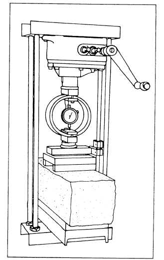
Figure 13-24.—Flexural-strength testing assembly for 6-inch
by 6-inch by 21-inch concrete beam.
For each tested specimen, your test report should
include the identification, diameter, length, maximum
load, compressive strength, irregular fracture or defect
in caps or specimen, and age of specimen at test. Report
the average compressive strength of all cylinders from
the same concrete sample.
Flexural-Strength Test (ASTM C 78)
Flexural strength is the ability to resist an applied
bending force such as encountered by concrete
pavements or other slabs on ground. A determination of
the flexural strength is frequently necessary as part of
the design of concrete mixtures to check compliance
with established specifications or to provide informa-
tion necessary to the design of an engineering structure.
In the flexural-strength test, a test load is applied to
the sides of a test beam. Although the test can be
performed upon beams sawed from existing concrete
structures, it is more commonly performed upon beams
Figure 13-25.—Alternate testing assembly using CBR test
equipment.
that are cast for testing purposes. The standard test beam
measures 6 inches by 6 inches by 21 inches. When
performing the test for mix-design purposes, you will
need at least five beam specimens for each mixture
design being evaluated. Two of the specimens are
broken at 7 days to permit an early evaluation of the mix.
The remaining beams are broken at 28 days. The
procedures for preparing test beams is discussed in the
EA3 TRAMAN. If necessary, you should review those
procedures. The following paragraphs discuss only the
procedures used to perform the test.
When performing the flexural-strength test, you use
a concrete beam tester with third-point loading. An
example of that equipment is illustrated in figure 13-24.
An alternate testing assembly can be made from the
loading frame and certain attachments provided with the
California bearing ratio (CBR) test set, the breaker
(third-point loading), and the 10,000-pound capacity
proving ring. That alternate assembly is shown in figure
13-25.
13-32


