Figure 6-8.—Adjusting the telescope level.
1. Sight the vertical cross hair on some high point,
A, at least 30° above the horizontal and at a distance of
200 feet, such as the tip of a church steeple or other
well-defined object, and clamp the plates.
2. Depress the telescope and mark a second point,
B, at about the same level as the telescope.
3. Plunge the telescope, unclamp the lower plate,
and rotate the instrument about its vertical axis.
4. Sight on the first point, A.
5. Clamp the lower plate and depress the
telescope. If the vertical cross hair intersects the second
or lower point, B, the horizontal axis is in adjustment.
In this case, point B is coincident with point D in both
direct and reverse positions of the telescope.
6. If not, mark the new point, C, on this line and
note the distance, BC, between this point and the original
point.
7. Mark point D exactly midway of the distance
BC. CD is the amount of correction to be made.
8. Adjust the horizontal axis by turning the small
capstan screw in the adjustable bearing at one end of the
horizontal axis until point C appears to have moved to
point D.
9. Repeat this test until the vertical cross hair
passes through the high and low points in the direct and
inverted position of the telescope.
10. Check all previous adjustments.
NOTE: When you cannot immediately correct the
above condition, you can compensate by repeating any
survey procedure with the telescope reversed and then
use the average of the results.
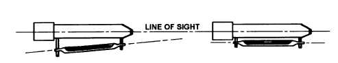
ADJUSTING THE TELESCOPE LEVEL.— To
be able to use a transit for direct leveling and to measure
vertical angles without index error, you must ensure that
the axis of the telescope level is parallel to the line of
sight. To adjust the telescope level of the transit, use the
same two-peg method that we discussed previously for
the engineer’s level. The only difference is that you must
level the telescope carefully before each reading. After
computing the reading that should be made on the far
rod (fig. 6-3), you set the horizontal cross hair on the
computed reading using the vertical slow motion screw.
Then you move one end of the spirit level vertically by
means of the adjusting nuts until the bubble is centered
in the tube (fig. 6-8).
NOTE: As with the engineer’s level, you should
compensate for the above maladjustment by careful
balancing of all backlights and foresights.
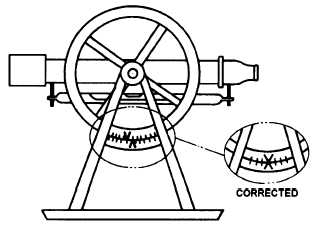
ADJUSTING THE VERTICAL CIRCLE
VERNIER.— For vertical angles to be measured
without index error caused by displacement of the
vertical circle vernier, the vernier should read zero when
the plate bubbles and telescope bubbles are properly
leveled. To make the vertical circle vernier read zero
when the instrument is leveled (fig. 6-9), you should
perform the following steps:
1. With the plate bubbles leveled, bring the
telescope bubble to the center of the tube and read the
vernier of the vertical circle.
2. If the vernier does not read zero, loosen the
capstan screws holding the vernier and move the index
until it reads zero on the vertical circle.
3. lighten the screws and read the vernier with all
the bubbles in the center of their tubes to make sure that
Figure 6-9.—Adjusting the vertical circle vernier.
6-8