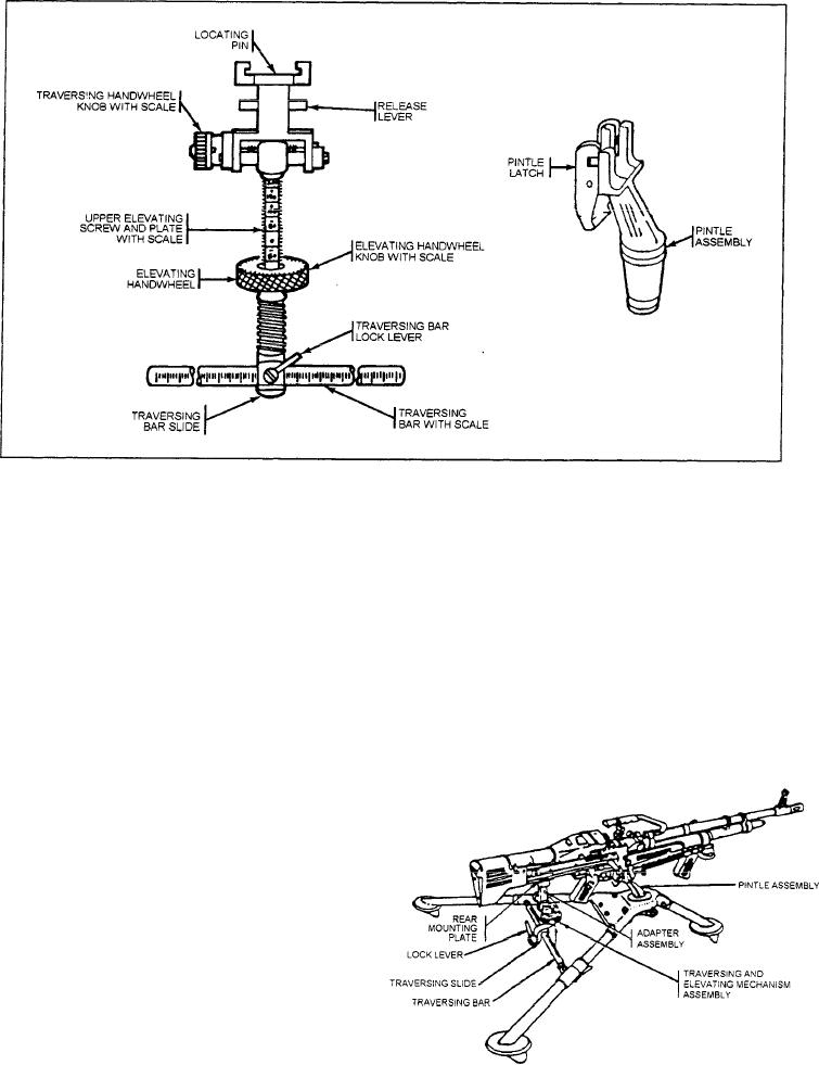
Figure 13-12.--Traversing and elevating mechanism, pintle, and platform group.
connects the traversing bar and a rear leg to permit the
The traversing slide lock lever allows rapid lateral
legs to fold. Position stops are provided to stop the
adjustments along the traversing bar. Readings are taken
traversing bar in the open or closed positions. The sleeve
from the left side of the slide.
latch on the right rear leg secures the traversing bar when
The pintle and platform group shown in figure
in the open position. (See fig. 13-11.)
13-12 consist of the gun platform and the pintle, which
The traversing and elevating mechanism shown in
is secured to the tripod assembly.
figure 13-12 consists of (1) the elevation adapter that
To mount the gun, (1) lock the pintle and platform
connects to the mounting plate on the bottom of the
group into the pintle bushing, as shown in figure 13-13;
receiver and (2) the traversing handwheel that has a
roil-click device built into it. One click equals a l-mil
change. Engraved on the traversing handwheel is a scale
that is divided into l-mil increments for a total of 25
mils. Use of the traversing mechanism allows the gun to
be traversed approximately 100 mils (50 mils right and
left of center).
The elevating handwheel has a mil-click device
built into it. One click equals a 1-mil change. Engraved
on the handwheel is a scale divided into 5-mil major
divisions and 1-mil subdivisions. The scale is read
directly from the indicator. The upper elevating screw
has the elevating screw plate, which is graduated into
50-mil increments. There are 200 mils above and 200
mils below the zero mark for a total of 400 mils in
Figure 13-13.--Gun in relation to the tripod.
elevation change.
13-8

