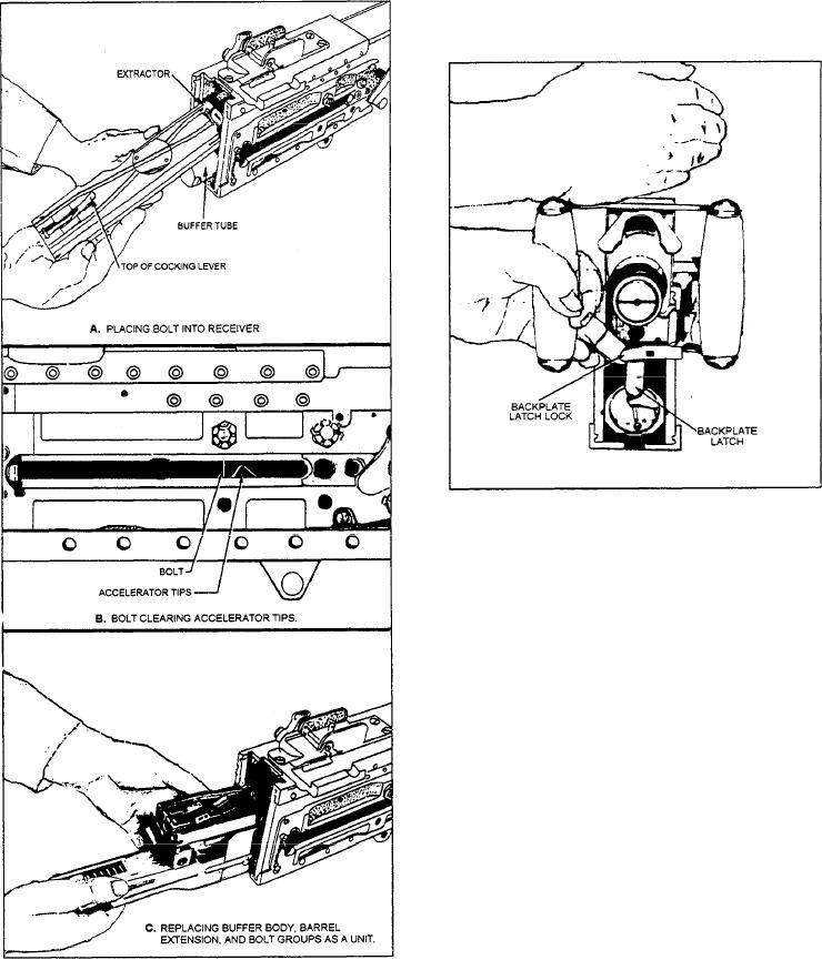
Figure 13-46.--Replacing the backplate assembly.
View C of the figure shows an optional procedure.
The buffer body, barrel extension, and bolt groups can
be assembled outside the receiver. Then, all three groups
are inserted as a single unit.
Replace Bolt Stud
The actions required to replace the bolt stud are
almost the same as those required to remove it. (See fig.
13-39.) Align the stud hole in the bolt with the clearance
hole in the right sideplate. Ensure the shoulder of the
stud fits inside the sideplate.
Replace Driving Spring Group
To replace the driving spring group, press up on the
bolt latch. Move the bolt all the way forward by pushing
on the bolt stud only. Place the end of the driving spring
rod in its hole in the back of the bolt. Then push forward
on the driving spring group and the buffer tube. Press in
and push the head of the rod to the right. Insert the
retaining pin in its seat in the right sideplate. (See fig.
Figure 13-45.--Replacing the bolt group.
13-38.)
forward and the extractor must be down (flat), as shown
Replace Backplate Assembly
in view A.
To replace the backplate, hold its latch down and the
Push the bolt forward, maneuvering it so the front
trigger up. Position the backplate guides in their
end clears the accelerator tips, as shown in view B. That
guideways. Hold the latch lock out and slide the
condition can be seen through the sideplate of the
backplate down until the latch snaps into place, as shown
in figure 13-46. Release the latch lock and tug up on the
receiver. Continue pushing the bolt forward until the bolt
backplate assembly to ensure it is firmly seated.
latch engages the notches in the top of the bolt.
13-25

