
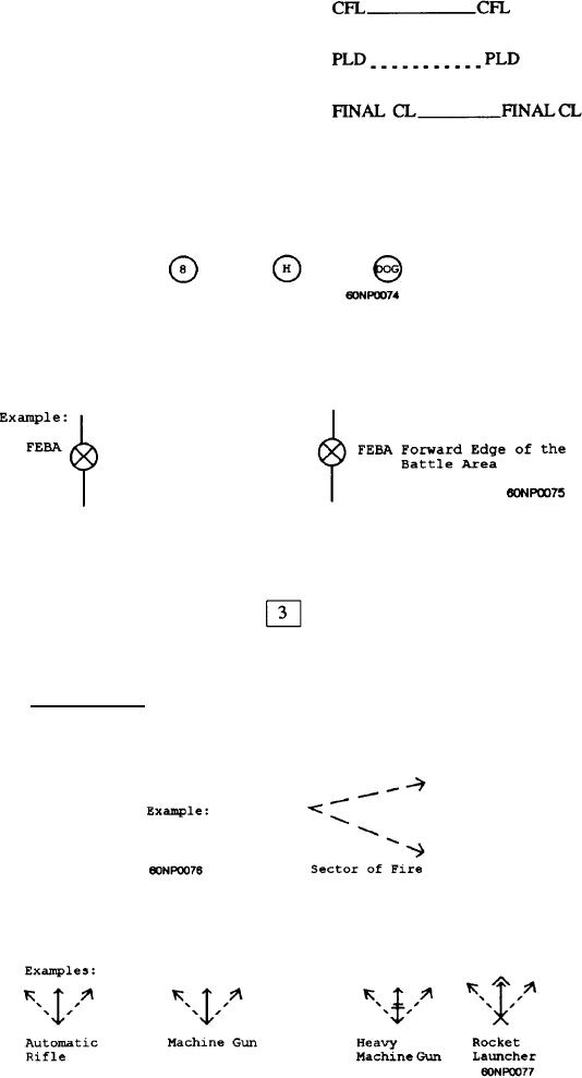
(8) Coordinated fire line
(9) Probable line of deployment
(10) Final coordination line
b. Control points are drawn on the selected terrain feature and identified as
follows:
(1) A checkpoint consists of a circle enclosing a selected terrain feature
with a number, letter, or code name placed inside the circle.
(2) A coordinating point is shown by drawing a circle on the selected
terrain feature and placing an "X" in the center. Coordinating points are used in
conjunction with boundaries to designate defensive areas.
(3) A contact point is shown by drawing a square with a number placed
inside.
4. FIRE PLANS
a. Sector of Fire
(1) Representation of a sector of fire is shown by two arrows composed
of broken lines:
(2) A weapon symbol is normally used in conjunction with the symbol
for a sector of fire. The base of the symbol indicates the weapon's position.
AII-4