CHAPTER 11
HORIZONTAL AND VERTICAL CURVES
As you know from your study of chapter 3, the
center line of a road consists of series of straight lines
interconnected by curves that are used to change
the alignment, direction, or slope of the road. Those
curves that change the alignment or direction are
known as horizontal curves, and those that change
the slope are vertical curves.
As an EA you may have to assist in the design of
these curves. Generally, however, your main concern
is to compute for the missing curve elements and parts
as problems occur in the field in the actual curve
layout. You will find that a thorough knowledge of the
properties and behavior of horizontal and vertical
curves as used in highway work will eliminate delays
and unnecessary labor. Careful study of this chapter
will alert you to common problems in horizontal and
vertical curve layouts. To enhance your knowledge
and proficiency, however, you should supplement
your study of this chapter by reading other books
containing this subject matter. You can usually find
books such as Construction Surveying, FM 5-233,
and Surveying Theory and Practice, by Davis, Foote,
Anderson, and Mikhail, in the technical library of a
public works or battalion engineering division.
HORIZONTAL CURVES
When a highway changes horizontal direction,
making the point where it changes direction a point of
intersection between two straight lines is not feasible.
The change in direction would be too abrupt for the
safety of modem, high-speed vehicles. It is therefore
necessary to interpose a curve between the straight
lines. The straight lines of a road are called tangents
because the lines are tangent to the curves used to
change direction.
In practically all modem highways, the curves are
circular curves; that is, curves that form circular arcs.
The smaller the radius of a circular curve, the sharper
the curve. For modern, high-speed highways, the
curves must be flat, rather than sharp. That means
they must be large-radius curves.
In highway work, the curves needed for the loca-
tion or improvement of small secondary roads may
be worked out in the field. Usually, however, the
11-1
horizontal curves are computed after the route has
been selected, the field surveys have been done, and
the survey base line and necessary topographic fea-
tures have been plotted. In urban work, the curves of
streets are designed as an integral part of the prelimi-
nary and final layouts, which are usually done on a
topographic map. In highway work, the road itself is
the end result and the purpose of the design. But in
urban work, the streets and their curves are of second-
ary importance; the best use of the building sites is of
primary importance.
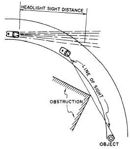
The principal consideration in the design of a
curve is the selection of the length of the radius or the
degree of curvature (explained later). This selection is
based on such considerations as the design speed of
the highway and the sight distance as limited by head-
lights or obstructions (fig. 11-1). Some typical radii
you may encounter are 12,000 feet or longer on an
interstate highway, 1,000 feet on a major thorough-
fare in a city, 500 feet on an industrial access road, and
150 feet on a minor residential street.
Figure 11-1.—Lines of sight.