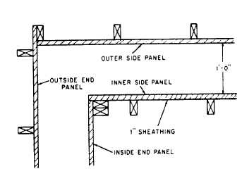
Figure 7-33.-Method of joining wall form
corner.
panels at a
them off the inner sections of rod with a special
wrench leaving the cone-shaped surface holes. The
outer sections and the cone nuts may be reused
indefinitely.
The use of prefabricated panels for formwork
has recently been on the increase. These panels
can be reused many times, thus reducing the time
and labor required for erecting forms on the
site.
Many types of prefabricated form panels are
in use. Contractors sometimes build their own
panels from wood framing covered with plywood
sheathing (fig. 7-33). The standard size is 2 ft by
8 ft, but panels can be sized to suit any particular
situation.
Panels made with a metal frame and plywood
sheathing are also in common use and are
available in a variety of sizes. Special sections
are produced to form inside corners, pilasters,
and so forth. Panels are held together by
patented panel clamps. Flat bar ties, which lock
into place between panels, eliminate the need for
spreaders. Forms are aligned by using one or more
doubled rows of 2 by 4's, secured to the forms
by a special device that is attached to the bar
ties.
Form panels made completely of steel are also
available. The standard size is 24 by 48 in., but
various other sizes are also manufactured. Inside
and outside corner sections are standard, and
insert angles allow odd-sized panels to be made
up as desired.
Large
placement
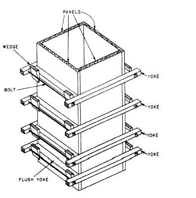
Figure 7-34.-Column form.
projects requiring mass concrete
are often formed by the use of giant
panels or ganged, prefabricated forms. Cranes
usually raise and place these large sections,
so their size is limited only by the available
equipment. These large forms are built or
assembled on the ground, and their only basic
difference from regular forms is the extra
bracing required to withstand handling.
Special attention must be given to corners
when forms are being erected. These are weak
points because the continuity of sheathing and
wales is broken. Forms must be pulled tightly
together at these points to prevent leakage of
concrete.
Column Forms
A typical concrete column form (fig. 7-34) is
securely braced by YOKES to hold the sheathing
together against the bursting pressure exerted on
the form by the plastic concrete. Since the bursting
pressure is greater at the bottom than the top, the
yokes are placed closer together at the bottom.
Notice, in figure 7-34, that on two panels, the
7-21


