traverse (sometimes called a P-line or survey base
line), establishing BMs, running profiles, and
taking cross sections. For many projects, the
preliminary survey may be conducted by a transit-
tape party alone. Other projects may require a
level party and a topographic party.
Normally, the data gathered from a preliminary
survey are plotted while the party is in the field,
This practice gives a more accurate representation
of the terrain, reduces the possibility of error, and
helps to resolve any doubtful situations while you
are actually observing the terrain.
FINAL-LOCATION SURVEY.— The final-
location survey, usually called the location,
constitutes a continuous operation; or, in other
words, the survey operation goes on from the start
of the project through to the end of the actual
construction. The location survey consists of
establishing the approved layout in the field, such
as providing the alignment, grades, and locations
that will guide the construction crew.
The EAs tasked with final-location survey
normally start (time and distance) ahead of the
construction crew. This is often done to save
construction time and to avoid delay of scheduled
activities. Some of these activities are setting
stakes to mark the limits of final earthmoving
operations to locate structures and establishing
final grades and alignment.
Before making the final-location survey, you
should make office studies consisting of the
preparation of a map from preliminary survey
data, projection of a tentative alignment and
profile, and preliminary estimates of quantities
and costs. Use this information as a guide for the
final location phase. The final location in the field
is carefully established by your transit party,
using the paper location prepared from the
preliminary survey. The center line may vary
from the paper location because of objects or
conditions that were not previously considered;
but these changes should not be made by you, the
surveyor, without the authority of the engineering
officer.
Office Work
After the type and general location of a
highway are decided and the necessary design data
is obtained in the field, a number of office tasks
must be performed. These tasks include the
following:
1. Plotting the plan view
2. Plotting the profile
3. Plotting the alignment
4. Designing the gradients
5. Plotting the cross sections
6. Determining end areas
7. Computing the volumes of cut and fill
Repeat these operations one or more times as
trial designs are developed and then revised or
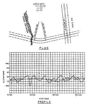
discarded. For a highway plan and profile, plot
on the same sheet. Figure 14-22 shows a plotted
highway plan and profile view. Plotting cross
sections is discussed later in this chapter.
PLOTTING THE PLAN VIEW.— Plotting
the plan view of a highway is similar to a traverse
except for the introduction of topographic details,
curves, and curve data. As a study of highway
curves and curve data is beyond the scope of this
TRAMAN (but will be studied at the EA2 level),
suffice it to say that the important elements of
the curve are shown in the form of notes at each
curve point. (See the plan view, figure 14-22.)
Figure 14-22.-Plan and profile for a highway.
14-27


