distribution and sanitary drainage systems
combined, especially on smaller buildings or
houses. The plumbing layout is usually drawn
into a copy of the floor plan for proper
orientation with existing plumbing fixtures,
walls and partition outlines, and other utility
features. Figure 8-27 shows a typical plumbing
layout. The reproduction is, unfortunately,
too small to be easily studied, but you can
see that it uses the mechanical symbols.
Refer to ANSI Y32.4-1977, Graphic Symbols
Used in Architectural and Building Construction
and MIL- STD-17-1, Mechanical Symbols.
As shown in figure 8-27, the cold-water
service line, which enters the building near the
laundry trays, is indicated by a broken dash-and-
single-dot line, while the waste pipes are indicated
by solid lines. If you follow the cold-water
service line, you will see how it passes, first, a 1-in.
main shutoff valve below the floor and just
inside the building wall. From here, it proceeds
to a long pipe running parallel to the building wall
and hung under the floor joists, which services,
beginning at the right-hand end, the cold-water
spigot in the sink, the cold-water spigot in the
laundry, the hot-water heater, the boiler for the
house heating system, the flushing system in the
water closet (W.C.), the cold-water spigot in the
bathroom washbasin, and the cold-water spigot
in the bathtub. The below-the-floor line is
connected to the spigots by vertical RISERS.
Valves at the hot-water heater and boilers are
indicated by appropriate symbols.
From the hot-water heater, you can trace the
hot-water line (broken dash-and-double-dot line)
to the hot-water spigots in the sink, laundry,
bathroom washbasin, and bathtub. This line is
also hung below the floor joists and connected
to the spigots by risers.
You can see the waste line (solid line) for the
bathtub, washbasin, and W.C. (with traps
indicated by bends) running under the floor from
the bathtub by way of the washbasin and W.C.
to the 4-in. sanitary sewer. Similarly, you can see
the waste line from the laundry running to the
same outlet. However, the kitchen sink has its
own, separate waste line. The bathroom utilities
waste lines vent through a 4-in. pipe running
through the roof; the sink waste line vents through
a 2-in. pipe running up through the roof.
MECHANICAL SYMBOLS
As stated earlier in this chapter, the Engineer-
ing Aid is not expected to design the system, but
the main objective is to draw a workable
plumbing plan for use by the plumbing crew or
any other interested parties. In order to
accomplish this, the EA must be familiar with the
terms, symbols, definitions, and the basic
concepts of the plumbing trade.
As a rule, plumbing plans should show the
location of the fixtures and fittings to be
installed and the size and the route of the
piping. The basic details are left to the plumber
(UT), who is responsible for installing a
properly connected system according to applicable
codes, specifications, and good plumbing and
construction practices. Generally, plumbing plans
consist of four types of symbols: piping, fittings,
valves, and fixtures.
Piping Symbols
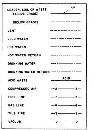
The line symbols for piping shown in figure
8-28 are composed of solid or dashed lines that
indicate the type and location of that particular
Figure 8-28.-Line symbols for piping.
8-21


