Branches
Solid and waste pipe BRANCHES are
horizontal branch takeoffs that connect various
fixtures and the vertical stack (fig. 8-19). One
method of installing a branch takeoff from the
vertical stack is to use a Y-branch with a 1/8 bend
caulked into it. Another method is to use a
sanitary tee, which is an extra-short-pattern 900
Y-branch. Of these two methods, the sanitary tee
is better because you eliminate one fitting and an
extra caulked joint, both of which arc required
for the 1/8 bend takeoff.
In some cases, however, the combination
Y and 1/8 bend is used more often than the
sanitary tee when local codes allow more fixture
units to be connected to a stack of a given
size.
Generally, waste pipes are graded downward
to ensure complete drainage. Horizontal vents are
also pitched slightly to facilitate discharge of
condensation.
MECHANICAL PLAN
A mechanical plan, as used in this chapter,
includes drawings, layouts, diagrams, and notes
that refer only to water distribution and sanitary
drainage systems. Heating and air conditioning,
refrigeration, and other like systems will not be
discussed in this section. In the Navy, mechanical
systems vary, depending on whether these systems
are aboard ship or shore-based. As an EA, you
will be mainly concerned with the shore-based
systems, which may be permanent installations
with the most modern fixtures, equipment, and
appurtenances, or temporary installations at
advanced bases. For temporary installations, the
most economical materials that will serve the
purpose are normally used.
WATER SUPPLY AND
DISTRIBUTION DIAGRAM
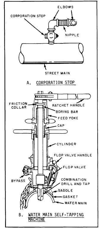
The water supply system for a building starts
from a single source—the water main. Water is
tapped from this source with a self-tapping
machine (fig. 8-23, view B), and a corporation
stop (fig. 8-23, view A) is installed. Cold water
enters the building through a cold-water service
Figure 8-23.-Use of corporation stop and self-tapping
machine.
8-17


