line. Figure 8-24 shows typical hot- and cold-water
service lines for a single-story residential building
and how they are connected to feed the fixtures.
This type of layout is often called a RISER
DIAGRAM. This diagram, in isometric, is a
method of visualizing or showing a three-
dimensional picture of the pipes in one drawing.
WASTE AND SOIL
DRAINAGE DIAGRAM
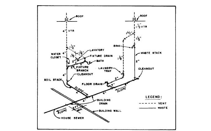
Figure 8-25 shows the waste and soil pipes and.
associated fitting symbols in a riser diagram. The
arrow represents the direction of flow. If you
notice, all the pipes are sloping towards the
building drain. Figure 8-26 further shows the basic
layout of a drainage system. The function of each
part is as follows:
. FIXTURE BRANCHES are horizontal
drainpipes connecting several fixtures to the stack.
. A FIXTURE DRAIN extends from the
P-trap of a fixture to the junction of that drain
with any other drainpipe.
l S O I L A N D W A S T E F I X T U R E
BRANCHES feed into a vertical pipe, referred
to as a stack. If the waste carried by the fixture
branch includes human waste (coming from water
closets or from a fixture with similar functions),
the stack is called a SOIL STACK. If a stack
carries waste that does not include human waste,
it is referred to as a WASTE STACK. These
stacks service all the fixture branches beginning
at the top branch and go vertically to the building
drain.
. A BUILDING DRAIN (also referred to as
a house drain) is the lowest piping part of the
drainage system. It receives the discharge from
the soil, waste, and other drainage pipes inside
the building and extends to a point 3 ft outside
the building wall. (Most local codes require that
the house drain extend at least 3 ft beyond the
building wall, but a few local requirements range
from 2 to 10 ft.)
. A BUILDING SEWER is that part of the
horizontal piping of a drainage system that
extends from the end of the building drain. It
Figure 8-26.-Basic layout of a drainage system.
8-19


