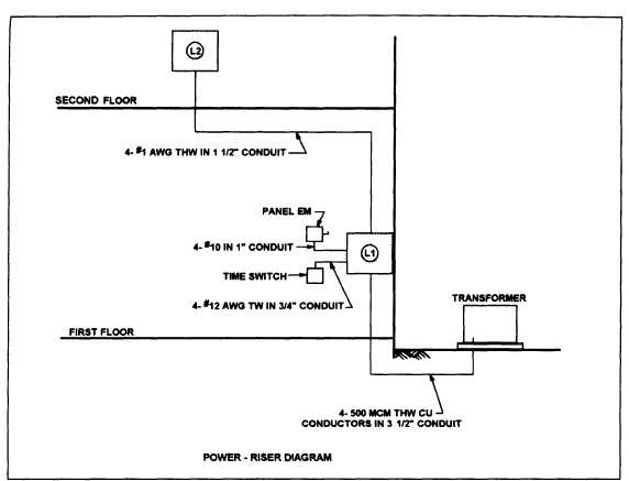
Figure 4-3.—Example of a power-riser diagram.
A simple example is the power-riser diagram shown
in figure 4-3. In this example, you see the manner in
which two electrical panels (L1 and L2) are planned for
installation in a two-story building. As you see, notes
are used to identify each piece of equipment and to
indicate the number, size, and type of conductors in each
conduit. A panelboard schedule for each of the panels
should also be included in the drawings to indicate the
components, such as fuses or circuit breakers, contained
in the each panelboard.
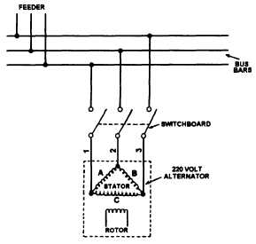
A schematic wiring diagram is similar to the
single-line block diagram; however, it provides more
detailed information and the actual number of wires
used in each circuit is shown. Complete schematic
wiring diagrams are usually used for unique and
complicated systems, such as control circuits. An
example of a schematic diagram is shown in figure 4-4.
FIRE PROTECTION DIVISION
This division includes the plans, details, and
schedules that describe the fire protection systems that
are to be installed in the building. These systems can
include, as applicable, wet-pipe or dry-pipe sprinkler
systems, monitoring equipment, and alarms. A
discussion of these systems is beyond the scope of this
TRAMAN.
Figure 4-4.—Example of a schematic diagram
HVAC SYSTEMS AND DRAWINGS
Although it’s the engineers responsibility to design
heating, ventilating, and air-conditioning systems, the
drafter who prepares drawings of the systems should
have a basic understanding of the operating principles
of each. Those principles, and a typical heating and air
conditioning layout for a building, are discussed in the
4-4