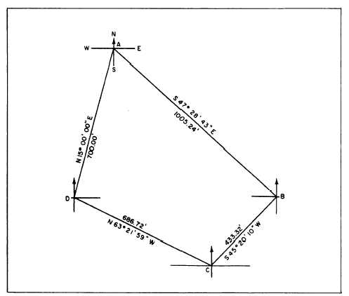
Figure 15-29.-Bearing and distances of a quadrilateral.
Thus we have, by computation of two routes, values
The following paragraphs explain how to determine the
for BC of 433.322 feet and 433.315 feet. There is a
discrepancy here of 0.007 feet For third-order work this
would usually be considered within tolerable limits; and
the computed value of BC would be taken to be the
average between the two, or (to the nearest 0.01 foot)
433.32 feet.
Suppose, now, that the precision requirements for
the base line check are 1/5,000. This means that the ratio
between the difference in lengths of the measured and
computed base line must not exceed 1/5,000. You
measure the base line BC and discover that it measures
433.25 feet. For a ratio of error of 1/5,000, the maximum
allowable error (discrepancy between computed and
measured value of base line) is 433.25/5,000, or 0.08
feet. The error here is (433.32 – 433.25), or 0.07 foot,
which is within the allowable limit.
LOCATIONS OF POINTS
The end result desired in a triangulation survey is
the horizontal locations of the points in the system, by
bearing and distance. Methods of converting deflection
angles to bearings and converting bearings to exterior
or interior angles are described in the EA3 TRAMAN.
bearings of lines of a quadrilateral.
Bearing and Distance
Figure 15-29 shows the quadrilateral we have been
working on, with the computed values of the sides
inscribed. Take station D as the starting point. Suppose
that, by an appropriate method, you have determined the
bearing of DA to be N15°00´00´´E, as shown. To have a
good picture of how you proceed to compute for the
bearing of the next line, AB, you must superimpose the
meridian line through the starting point, laying off
approximately the known bearing; in this case,
N15°00´00´´E. Now draw your meridian through point
A. From figure 15-29 you can see that the line AB bears
southeast, and you can find its bearing by subtracting
15°00´00´´ from angle A. Angle A is the sum of angles 1
and 2 (38°44´08´´ + 23°44´35´´), or 62°28´43´´, as you
should recall from figure 15-28. The bearing angle of
AB, then, is 62°28´43´´ – 15°00´00´´, or 47°28´43´´.
Therefore, the complete bearing of line AB is
S47°28´43´´E.
15-39


